Warning, Caution, 3 - assembly instructions – McCulloch MCM2013 User Manual
Page 6
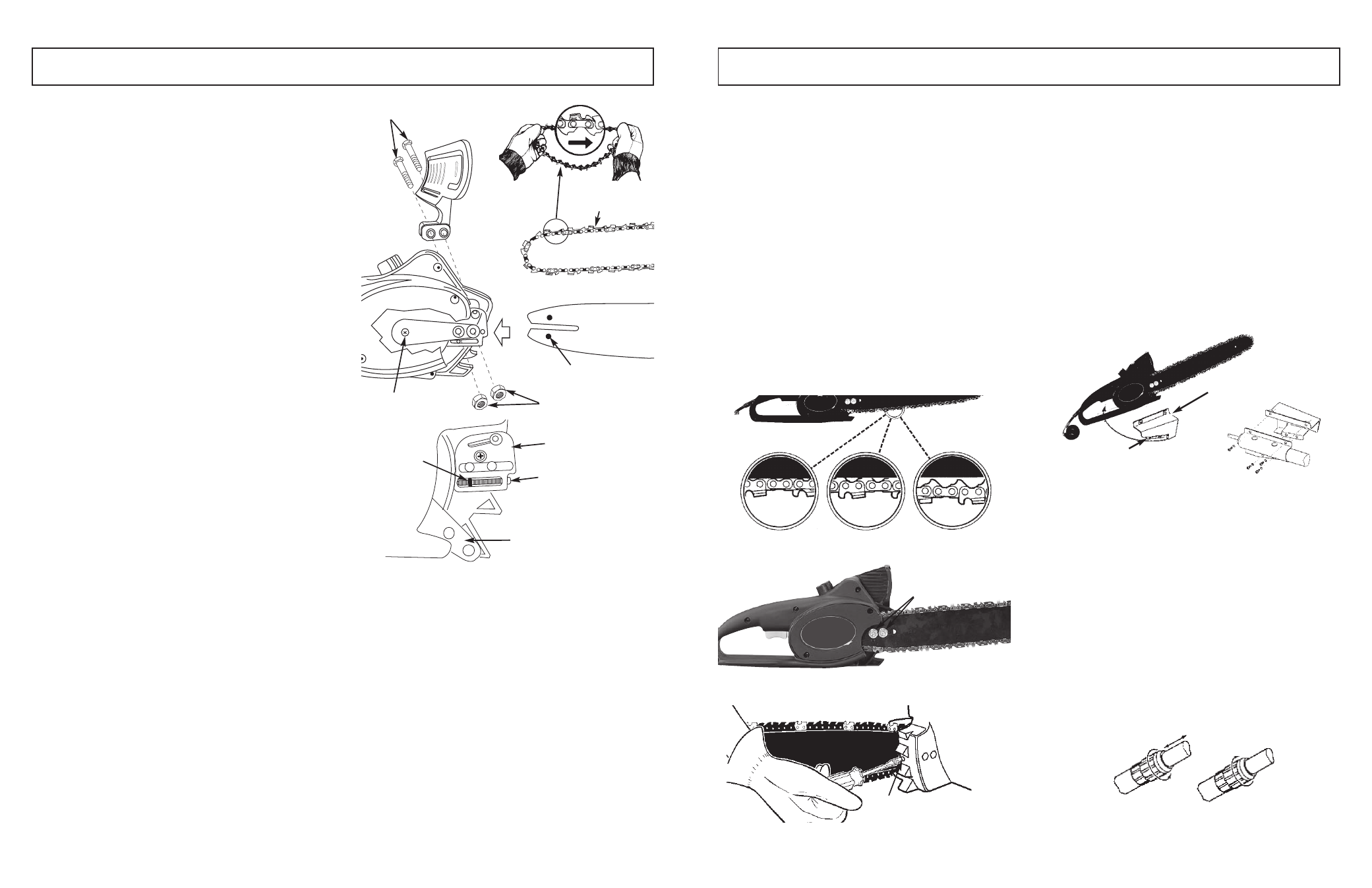
TO ADJUST SAW CHAIN TENSION:
1. Loosen the bar retaining nuts (D) so they are hand
tight. (See Fig. 3-5B)
2. Holding the nose of the bar up, use the screwdriver or
scrench if provided in your User’s Kit to turn the guide
bar adjustment screw (E) (Fig. 3-5C) clockwise to
tighten the chain. Turning the screw COUNTER-
CLOCKWISE LOOSENS THE CHAIN on the guide
bar.
3. After adjustment and while wearing heavy duty work
gloves, move the saw chain back and forth on the
guide bar to be sure the chain moves freely and is in
proper mesh with sprocket. Do not move chain with
bare hands.
NOTE: IF the chain is difficult to rotate or if it binds on the
guide bar, too much tension has been applied and must be
adjusted. To decrease tension, turn the adjustment screw
counterclockwise slowly. Move the chain back and forth
until it moves freely.
4. Holding the nose in upper position, securely tighten the
bar retaining nuts (70 inch lbs.)
3-6. ASSEMBLY OF POLE SAW
1. Make sure the unit is unplugged from power source.
2. Slip handle bracket (A) over chain saw handle from
the right side (See Fig. 3-6A). NOTE: The trigger must
be depressed before the bracket will go onto the han-
dle. Push the lock-off button and depress the trigger.
While holding the trigger in, place the trigger support
portion of the bracket under the trigger and slide the
bracket onto the chain saw handle. The bracket will
keep the trigger in the “ON” position.
3. Align holes in pole bracket with holes in handle brack-
et. Install Phillips head screws with lock washers
through pole bracket from left side and thread into the
weld nuts on the handle bracket. Tighten screws
securely.
4. Plug the saw power cord into receptacle cord at end
of inner pole.
3-7. ADJUSTING POLE LENGTH
The pole saw has a telescoping pole assembly that will
extend from 57 inches (fully retracted) to 96 inches (fully
extended). A threaded compression coupling is used to
hold the pole in position at any extended length.
1. To extend the pole, loosen coupling by turning cou-
pling nut counterclockwise as shown in Fig. 3-7A. Pole
will slide freely.
2. Pull inner pole section out to desired length of exten-
sion. Note: Only extend pole to minimum length
required to reach limb that is being cut.
3. To lock pole in position, tighten coupling by turning
coupling nut clockwise (See Fig. 3-7A) until firmly
hand tight. Make sure saw handle is aligned with pole
handle before tightening coupling nut.
IMPORTANT: Do not use wrench or pliers to over-
tighten coupling. Damage to coupling or pole may
result.
10
11
3 - ASSEMBLY INSTRUCTIONS
3-5A
3-1. INTRODUCTION
This unit is designed for occasional homeowner use and
should not be used for commercial purposes or subjected
to heavy continuous use.
Your new chain saw can be used for a variety of projects
such as cutting firewood, making fence posts, felling small
trees, limbing, pruning at ground level, and light carpentry.
Cut only wood or wood products with your saw.
3-2. UNPACKING
1. Remove all items from carton.
2. Check all items for any shipping damage. If you find
any damage or if any parts are missing, promptly
inform dealer where you bought the pole saw.
3-3. ASSEMBLY REQUIREMENTS
Your new pole saw will require adjustment of chain and fill-
ing the oil tank with lubricating oil before the unit is ready
for operation. Do not start the saw motor until the unit is
properly prepared.
Read all instructions carefully. Do not install any other size
bar and chain than what is recommended for your model.
3-4. GUIDE BAR / SAW CHAIN
REPLACEMENT INSTALLATION
WARNING
Whenever handling the saw chain, wear work gloves for
protection against sharp cutting edges.
1. Remove bar nuts, push bar bolts in and slide sprock-
et support down. (See Fig. 3-4A)
2. Remove old guide bar and chain.
3. Using a straight screwdriver, turn the chain adjust-
ment screw counterclockwise as far as it will go, or
until tang is to the end of its travel.
4. Loop saw chain over drive sprocket with the cutting
edges of the chain pointing in the direction of rotation.
5. Place the slotted end of guide bar over the bar bolt so
the tang fits into the lower hole in the guide guide bar.
6. Make sure the chain follows the slot in the guide bar.
Slide the sprocket support up and push the bar bolts
through the sprocket support.
7. Install the bar retaining nuts hand tight, (Proceed to
saw chain tension Adjustment).
3-5. SAW CHAIN TENSION ADJUSTMENT
Proper tension of the saw chain is extremely important and
must be checked before starting, as well as during, any cut-
ting operation. Taking the time to make needed adjust-
ments to the saw chain will result in improved cutting per-
formance and prolonged chain life.
NOTE: A new chain and bar will need readjustment after as
few as 5 cuts.This is normal during the break-in period, and
the interval between future adjustments will lengthen quick-
ly (Figure 3-5A).
CAUTION
If a chain is TOO LOOSE or TOO TIGHT, the bar chain and
saw bearings will wear more rapidly. Study Figure 3-5A for
information concerning correct cold tension (A), correct
warm tension (B), and as a guide for when saw chain
needs adjustment (C).
3 - ASSEMBLY INSTRUCTIONS
3-4A
Guide Bar Bolts
Saw Chain
Adjusting Plate
Drive Sprocket
Guide Bar Nuts
Guide Bar
Tang
Adjusting Screw
Sprocket Support
3-5B
D
A
B
C
3-5C
E
3-6A
A
B
3-7A
UNLOCK
LOCK
Adjusting Hole