Tip installation, Operation – Graco Inc. XTR 5 User Manual
Page 5
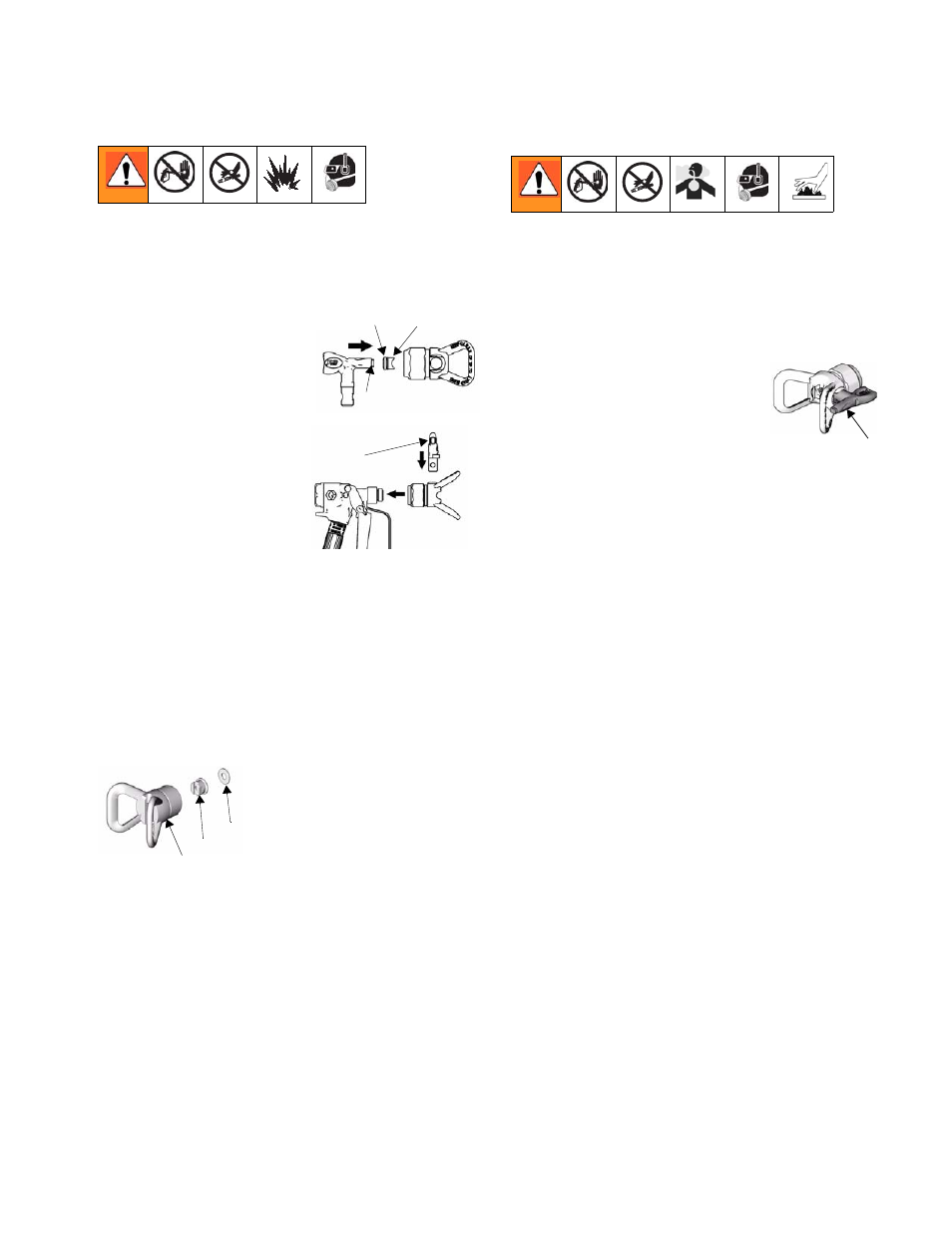
Tip Installation
312145D
5
Tip Installation
RAC Tip
1. Follow Pressure Relief Procedure.
Engage trigger lock.
2. Snap gasket (20b) on
fluid seal (20a). Use
tool (A) to insert
gasket and seal into
housing, seal first.
Tip the tool to remove
it when seal is in
place.
3. Install tip cylinder
(20c) as shown. Turn
90 ° counterclockwise
to spray position, so
the arrow faces
forward. Install assembled RAC onto spray
gun.
Flat Tip
1. Follow Pressure Relief Procedure.
Engage trigger lock.
2. Insert tip (32) and gasket (30) into back of
guard (31).
3. Install guard over end of gun.
Operation
1. Connect a grounded fluid hose.
2. Without spray tip, flush pump. Use lowest
pressure possible.
3. Prime. Refer to sprayer manual.
4. Follow Pressure Relief Procedure.
5. Install spray tip and tip guard.
6. RAC tips only: In spray
position, arrow on tip
cylinder (20c) faces
forward.
7. Hold gun perpendicular and approximately
12 inches (304 mm) from surface. Wear
gloves if fluid temperature exceeds 110°F
(43°C).
8. Move gun first, then pull gun trigger to
spray onto test paper.
a. Adjust fluid pressure until spray is com-
pletely atomized.
b. If adjusting pressure does not give a
good spray pattern, follow Pressure
Relief Procedure, then try another tip
size.
9. Trigger gun full-open or full-close.
Adjusting Spray Pattern
The spray tip orifice and spray angle determine
pattern coverage and size. When you need
more coverage, use a larger spray tip rather
than increasing fluid pressure.
1. Follow Pressure Relief Procedure.
Engage trigger lock.
2. Loosen tip guard retaining nut.
3. Align guard horizontally to spray a
horizontal pattern. Align guard vertically to
spray a vertical pattern.
4. Tighten nut.
20c
A
20a
20b
ti10635c
ti10051a
30
32
31
20c
ti11482a
ti10636b