1 generator control panel – Generac Power Systems 009600-5 User Manual
Page 9
Generac
®
Power Systems, Inc.
7
Section 2 – Operation
PRIMEPACT 66G and 66LP Recreational Vehicle Generators
1.6.4 ENGINE SPECIFICATIONS
Type of Engine
PRIMEPACT 66G/66LP ..............................................GN-480
Cooling Method ........................................................Air-cooled
Rated Horsepower
PRIMEPACT 66G/66LP ........................................16 at 3600
Displacement
PRIMEPACT 66G/66LP..................................................480cc
Compression Ratio........................................................8.6 to 1
Cylinder Block ..........................Aluminum w/Cast Iron Sleeve
Type of Governor ..............................Mechanical, Fixed Speed
Engine Governor Speed ............................................2700 rpm
Air Cleaner ........................Paper Element w/Foam Precleaner
Starter ........................................................12-volt DC Electric
Ignition System ......................Solid-state w/Flywheel Magneto
Recommended Spark Plug
Champion ..................................................................RC12YC
AC....................................................................................R45S
Fram Autolite ......................................................................65
Spark Plug Gap........................................0.030 inch (0.8 mm)
Recommended Min. Battery ............400 Cold Cranking Amps
1.6.5 EMISSIONS COMPLIANCE PERIOD
For nonhandled engines the Emissions Compliance
Period referred to on the Emissions Compliance
Label indicates the number of operating hours for
which the engine has been shown to meet Federal
emission requirements.
• For engines less than 225 cc displacement,
Category C=125 hours, B=250 hours, and A=500
hours.
• For engines of 225 cc or more, Category C=250
hours, B=500 hours, and A=1000 hours.
2.1
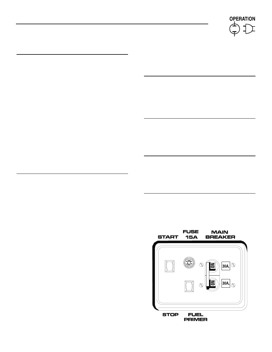
GENERATOR CONTROL PANEL
The following features are mounted on the generator
control panel (Figure 2.1):
2.1.1 FUEL PRIMER
Before starting a cold engine (if it has not been start-
ed in more than two weeks), you must press this
switch for approximately ten seconds to bring fuel
from the tank to the fuel pump. This rocker type
switch springs back into its original position when
you release it.
2.1.2 START/STOP SWITCH
To crank and start the engine, hold this switch in the
START position. Release the switch when the engine
starts. To stop an operating engine, press and hold
the switch in the STOP position until the engine shuts
off. The switch center position is the RUN position.
2.1.3 15 AMP FUSE
The fuse protects the engine’s DC control circuit
against electrical overload. If the fuse element has
melted open due to overloading, the engine cannot be
cranked. If you must replace the fuse, use only an
identical 15 amp replacement fuse.
2.1.4 LINE BREAKERS
Protects generator’s AC output circiut against
overload, i.e., prevents unit from exceeding
wattage/amperage capacity. This unit has two 30-amp
breakers.
Figure 2.1 – Typical Control Panel
◆
◆
◆
◆
◆
◆