Installation instructions, Installation, Handling & disposal of fire ceramics – Stovax Steel Manhattan Log Effect Stove Range User Manual
Page 12: Fuelbed arrangements
4. HANDLING & DISPOSAL OF FIRE CERAMICS
The fuel effect and side panels in this appliance are made
from Refractory Ceramic Fibre (RCF), a material which is
commonly used for this application.
Protective clothing is not required when handling these
articles, but we recommend you follow normal hygiene rules
of not smoking, eating or drinking in the work area and
always wash your hands before eating or drinking.
To ensure that the release of RCF fibres are kept to a
minimum, during installation and servicing a HEPA filtered
vacuum is recommended to remove any dust accumulated
in and around the appliance before and after working on it.
When servicing the appliance it is recommended that the
replaced items are not broken up, but are sealed within
heavy duty polythene bags and labelled as RCF waste.
RCF waste is classed as stable, non-reactive hazardous waste
and may be disposed of at a licensed landfill site.
Excessive exposure to these materials may cause temporary
irritation to eyes, skin and respiratory tract; wash hands
thoroughly after handling the material.
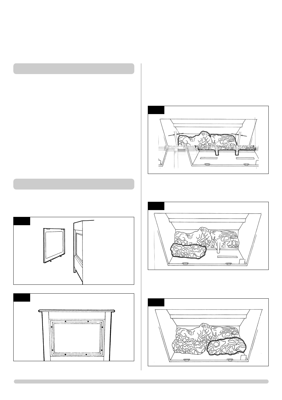
5. FUELBED ARRANGEMENTS
To gain access to the ceramic fuel pieces, it will be necessary
to remove the glass door. Lift off the decorative steel trim,
see Diagram 8 and remove the screws holding the glass
frame. See diagram 9.
INSTALLATION INSTRUCTIONS
INSTALLATION
The fuel bed consists of 5 logs and 2 ash panels. The logs
have letters A,B,C,D and E moulded into them for
identification.
5.1 Take the rear log A and place it up against the rear of the
fire sitting on the two flat ledges of the burner. The two legs
of the log should sit between the rear burner ports. See
diagram 10. Ensure an equal gap between each side of the
log and the side of the firebox.
5.2 Place log B on the left-hand side of the burner with the
location bar on the underside of the log fully located in the
long slot of the burner. Make sure the log is as far to the left
as possible. See diagram 11.
5.3 Place log C on the right-hand side of the burner with the
location bar on the underside of the log fully located in the
long slot in the burner. Make sure the log is as far right as
possible. See diagram 12.
12
AR1612
8
AR0883
9
AR0877
10
AR1610
11
AR1611