Installation instructions, Installation – Stovax Steel Manhattan Log Effect Stove Range User Manual
Page 11
11
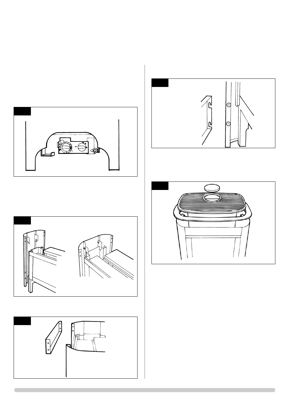
3.5 Having run the gas supply to the stove, PURGE THE SUPPLY
PIPE, this is essential to expel any debris that may block the
gas controls. Connect the gas supply to the 8mm
compression elbow at the right-hand rear corner of the
stove. There is a cutout in the right-hand rear leg to enable a
direct straight connection to be made to the rear of the
stove. See diagram 2. A gas soundness check must be
completed up to the gas inlet connection.
3.6 Open the second carton and carefully remove the steel
casing components. Remove the protective plastic coating
from the two side assemblies. Attach the four lugs to the
front side of each panel and lower them onto the engine
assembly until the tabs locate as shown. Check that the feet
are touching the hearth. See Diagram 3.
3.7 Secure the upper front panel using the 4 nuts and bolts
provided. See diagram 4.
3.8 Locate the lower panels onto the lugs as shown. See diagram
5.
3.9 Place the steel top onto the casing so that the 2 lugs on the
undeside locate the top centrally within the casing. Place the
cast iron grill into the recess in the centre of the top panel
and locate the blanking plate into the grill (if required). See
Diagram 6.
3.10 Check the pull of the flue system by applying a lighted
smoke pellet to the flue system opening. If there is a definite
flow into the chimney, proceed with the installation. If not,
warm the chimney for a few minutes.
IF THERE IS STILL NO DEFINITE FLOW, THE
FLUE MAY REQUIRE ATTENTION - SEEK EXPERT
ADVICE
3.11 The flue system may now be connected to the stove. Ensure
that all joints are sealed with a suitable fire resistant sealant.
It is also recommended that a physical retention method be
used at the flue spigot joint, self-tapping screws being
favoured.
3.12 Connect a suitable pressure gauge to the test point
located on the inlet fitting, and turn the gas supply on. Light
the appliance to maximum and check that the supply
pressure is as stated on the databadge. Turn the gas off and
replace the test point screw. Turn the gas on and check the
test point for gas soundness.
INSTALLATION INSTRUCTIONS
INSTALLATION
2
AR0934
5
AR0881
6
AR0882
4
AR080
3
AR0878
AR0879