On/off switch replacement, Wiring diagram – Graco 190ES 309063F User Manual
Page 17
17
309063
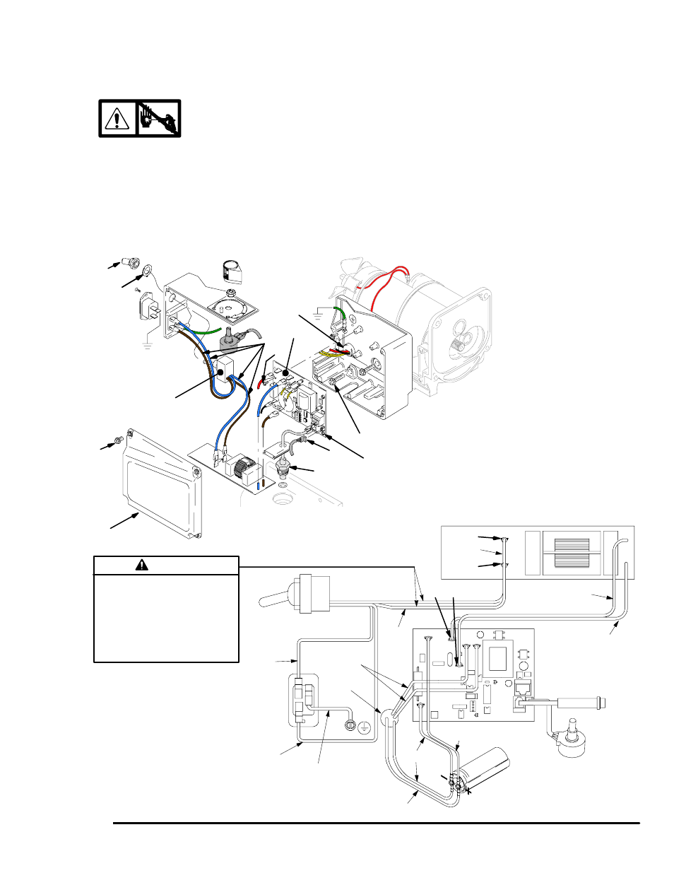
On/Off Switch Replacement
100 Vac (232903)
Removal
1.
Relieve pressure; page 6.
2. Fig. 13. Remove four screws (18) and pressure
control cover (39).
3. Disconnect four wires (A) from ON/OFF
switch (23).
4. Remove toggle boot (25) and locking ring (24).
Remove ON/OFF switch (23).
Installation
1. Install new ON/OFF switch (23). Install locking ring
(24) and toggle boot (25).
2. Connect four wires (A) to ON/OFF switch (23).
3. Install pressure control cover (39) with four
screws (18).
Fig.
13
TP1
TP2
L1
L2
ti0056b
39
A
18
23
36
52
E
D
35
25
24
37
Pressure
Transducer
ON/OFF
Switch
Power
Plug
Potentiometer
from Motor
Filter Board
Red (+)
Wiring Diagram
Heat from inductor coil of filter board
may destroy wire insulation that
comes in contact with it. Exposed
wires could cause shorts and com-
ponent damage. Bundle and tie all
loose wires so none lay in contact
with inductor coil of filter board.
Caution
Blue
Green/
Yellow
Brown
Yellow
Brown
TI0059
Capacitor
Blue
Red (+)
Black (--)
Brown
Blue
22