Graco Inc. Hydra-Clean 800-706 User Manual
Page 5
5
308–532
INSTALLATION
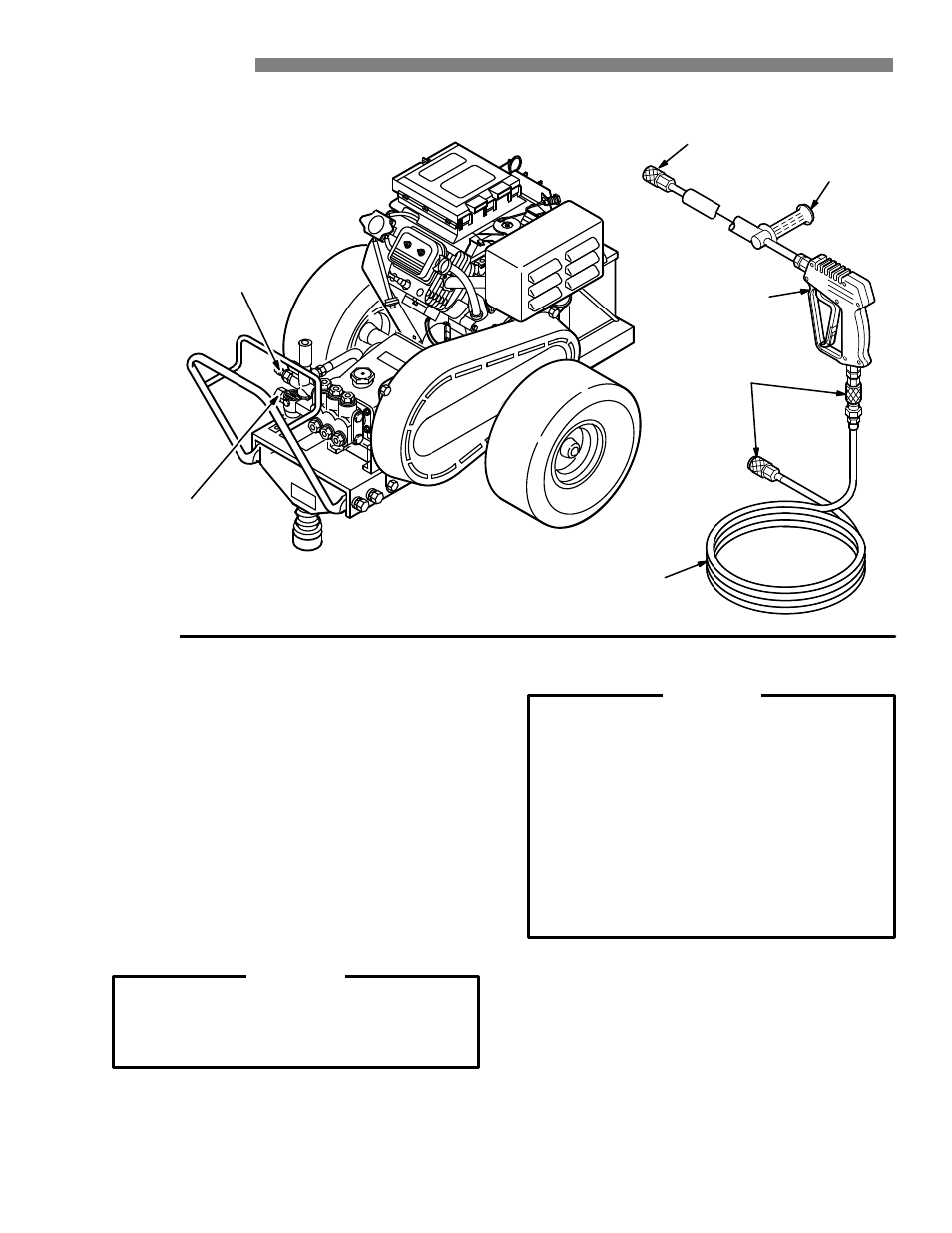
Figure 1
TEE HANDLE
(4043 ONLY)
SPRAY
GUN
SPRAY
HOSE
QUICK
COUPLER
QUICK
COUPLER
HIGH
PRESSURE
HOSE
CONNECTION
WATER
SUPPLY
CONNECTION
Check for Shipping Damage
Check the unit for any damage that may have occurred
in shipping.
Notify the carrier immediately if there is
any damage.
Set Up
Fill the battery cells with electrolyte and water. Charge
the battery. Be sure the battery connections are correct
and secure. Connect the fuel line to the engine using
the quick coupler provided. Squeeze the priming bulb 3
to 5 times. If you are using a downstream chemical
injector, install it between the pump unloader and the
high pressure hose, using the quick couplers provided.
Connect the high pressure hose between the pump
outlet and the gun inlet. Both of these connections are
made with quick couplers.
CAUTION
Up to 100 ft (30 m) of high pressure hose may
be used. Longer hoses may af
fect sprayer
performance, and chemical injector performance,
if used.
Install the appropriate spray tip on the wand.
See
Installing and Changing Spray Tips. If you are using a
sandblaster kit, see its separate manual for installation
instructions.
Connect to Water Supply
CAUTION
Before attaching to the water supply, check your
local plumbing code regarding cross– connection
to the water supply . A backflow preventer , P/N
801–133, is available to prevent backflow of
contaminated water into the fresh water supply .
Install it upstream from the pump.
If inlet water pressure is over 60 psi (4.1 bar) a
regulating water valve, P/N 800–258, must be
installed at the garden hose connection.
Do not exceed 160 _
F (70 _
C) inlet water
temperature.
Connect a hose with at least a 3/4 inch (19 mm) ID from
the water supply to the unit’s 3/4 inch garden hose inlet.
The supply hose should not be more than 50 ft (15 m)
long.
NOTE: The water source at the unit must have a
minimum flow rate equal to that of the unit
(see Technical Data, inside back cover).