Lifting & moving base unit, Assembly – Grizzly MOBILE PLANERS G0453 User Manual
Page 20
-18-
G0453/G0454 (Mfg. Since 3/08)
Lifting & Moving
Base unit
the Model G0453/G0454
is a heavy machine.
Serious personal injury
may occur if safe moving
methods are not used. to
be safe, get assistance
and use power equip-
ment to move the ship-
ping crate and remove the
machine from the crate.
the cabinet stand on the Model g0453/g0454
planer is equipped with four lifting bars that pull
out in order to lift and place the planer, as shown
in
figure 7.
figure 7. lifting the planer with a forklift.
lifting
Bar
(1 of 4)
tip: When positioning the lift forks, place shop
rags or cardboard between the forks and the cabi-
net stand to avoid scratching the paint.
Assembly
to assemble your planer:
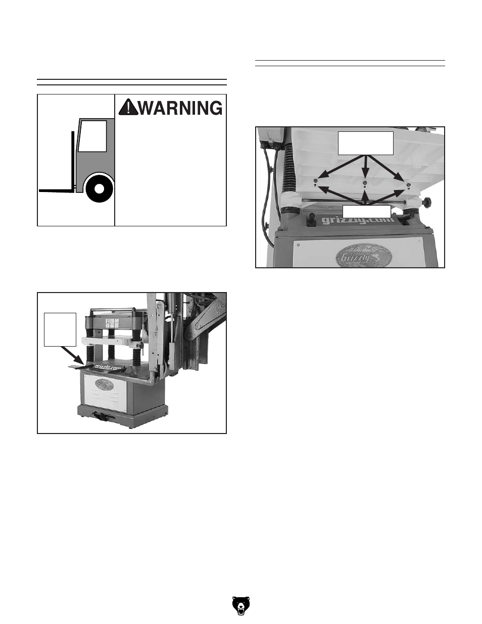
1. install M8-1.25 x 20 set screws in the holes in
the bottom of the wings (see
figure 8).
figure 8. Front extension wing installed (Model
g0454 shown).
set screws
hex Bolts &
Flat Washers
2. Attach the table extension wings to the planer
table with the M8-1.25 x 30 hex bolts, 8mm
lock washers, and 8mm flat washers, as
shown in
figure 8, but do not fully tighten the
bolts at this time.
3. using a straightedge as a guide and the
set screws for leveling control, position the
extension wings even with the table, then
fully tighten the hex bolts.
Note:
Be aware that the bed rollers will give
you a false reading with your straightedge if
they are raised above the table. Move them
down or work around them when leveling the
extension wings.
assembly