Greenheck Fan Make-Up Air Unit VSU User Manual
Page 3
3
Model VSU Make-Up Air
®
®
®
®
®
Table of Contents
Installation
Filter/Stand Section . . . . . . . . . . . . . . . . . . . . . .3-4
Burner/Blower Section . . . . . . . . . . . . . . . . . . . . . 4
Ductwork . . . . . . . . . . . . . . . . . . . . . . . . . . . . . . . . 4
Dimensional Data . . . . . . . . . . . . . . . . . . . . . . . . . 5
Direct Gas Piping . . . . . . . . . . . . . . . . . . . . . . . .6-7
Start-Up
Blower . . . . . . . . . . . . . . . . . . . . . . . . . . . . . . . . .8-9
Direct Gas . . . . . . . . . . . . . . . . . . . . . . . . . . . .10-12
Operation
Electrical . . . . . . . . . . . . . . . . . . . . . . . . . . . . . . . 13
Troubleshooting
Blower . . . . . . . . . . . . . . . . . . . . . . . . . . . . . . . . . 14
Heater . . . . . . . . . . . . . . . . . . . . . . . . . . . . . . .15-17
Maintenance
Routine . . . . . . . . . . . . . . . . . . . . . . . . . . . . . .18-19
Fall . . . . . . . . . . . . . . . . . . . . . . . . . . . . . . . . . . . . 19
Reference
Typical Control Center Layout . . . . . . . . . . . . . . 20
Typical Gas Train Layout . . . . . . . . . . . . . . . . . . . 20
Start-Up Check List . . . . . . . . . . . . . . . . . . . . . . 21
Maintenance Log . . . . . . . . . . . . . . . . . . . . . .22-23
Warranty . . . . . . . . . . . . . . . . . . . . . . . . .Backcover
Installation
1. Filter/Stand Section
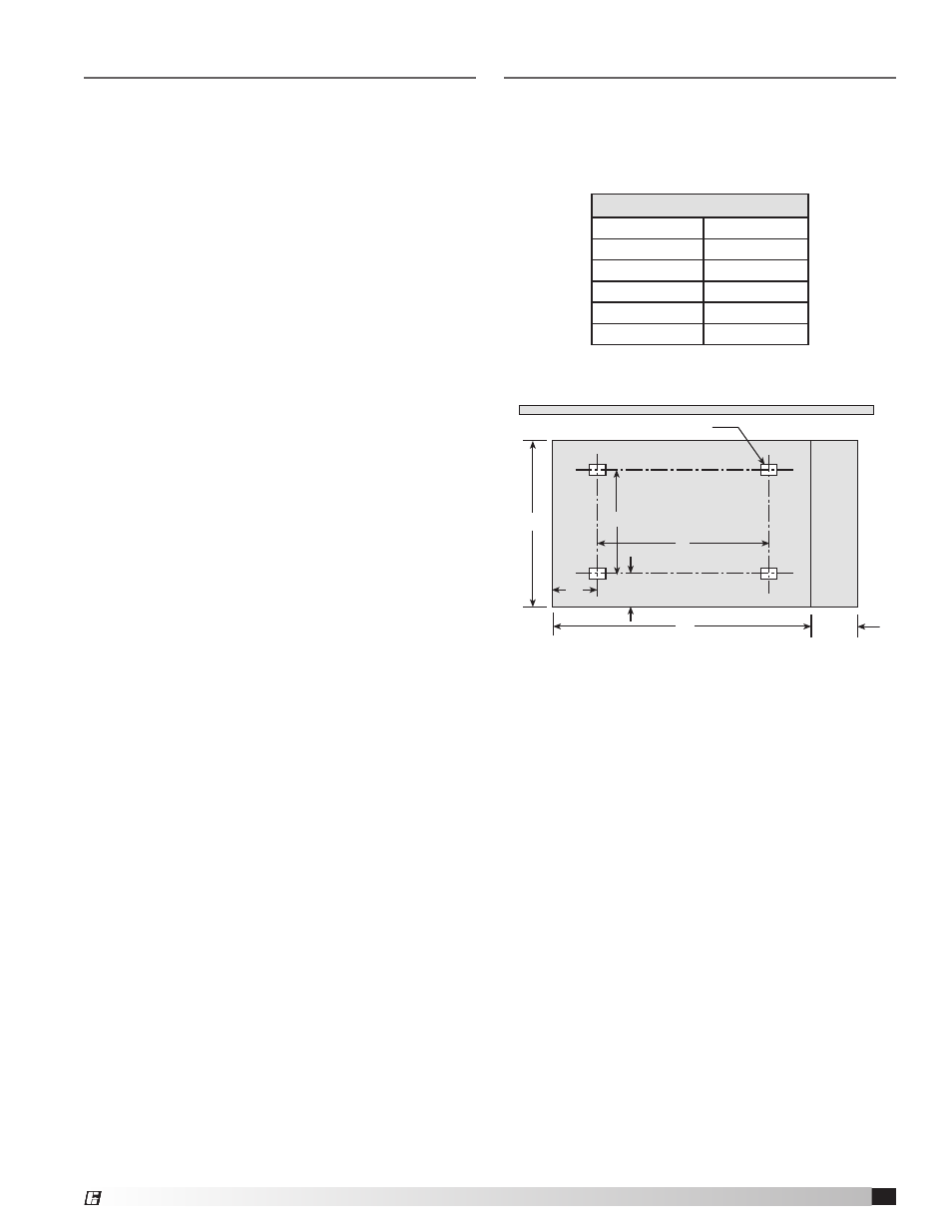
The unit should be mounted on a concrete slab four
inches thick with a proper gravel drainage bed. Allow
one foot on each side of the unit as shown in the
Concrete Slab and Unit Footprint drawing below.
The filter section ships inside the stand (see drawing
on next page). After the unit is set on the slab, it can
be anchored through the stand feet. The unit footprint
of the unit is shown above.
Greenheck recommends having a three foot clearance
on the controls side and a two foot clearance on the
other three sides of the unit for serviceability.
The following statement pertains to direct gas units
only. When ordered with insulation, this unit has a
zero-inch clearance tolerance to any combustibles,
on all sides and top. Without insulation, the clearance
tolerance is six inches.
Concrete Slab Dimensions
Housing Size
40
A
78
B
135
C
43
D
54
E
111
All dimensions are shown in inches.
Building Wall
A
B
C
Concrete Slab
Approx. Stand Feet Locations
Requir
ed with service
platform only
12
E
D
12
Unit Contr
ol Side
Concrete Slab and Unit Footprint