Aligning table – Grizzly 17" Heavy Duty-Bandsaw G0513X2BF User Manual
Page 38
-36-
G0513 Series Bandsaws
3. loosen the lateral rod cap screw and slide
the guide block to position the blade guides
approximately 0.016" behind the blade gul-
lets, as illustrated in
Figure 50.
Note: The 0.016" spacing is ideal, although
with larger blades it may not be possible.
In such cases, adjust the guide bearings as
far forward as possible to the blade gullets,
and still maintain the proper support bearing
spacing adjustment.
Blade
Gullet
Guide
Bearings
0.016"
Gap
Figure 50. lateral adjustment of blade guides.
4. tighten the lateral rod cap screw to secure
the setting.
5. loosen both bearing rotation cap screws.
6. rotate the knurled knob to position the bear-
ings approximately 0.004" away from the
blade.
7. re-tighten the cap screws to lock the blade
guide bearings in position.
Aligning Table
to ensure cutting accuracy when the table is first
installed, the table should be aligned so that the
miter slot is parallel to the bandsaw blade. this
procedure works best with a wide (
3
⁄
4
") blade
installed.
Tools Needed
Qty
straightedge ...................................................... 1
Fine ruler .......................................................... 1
square ............................................................... 1
Wrench or socket 13mm ................................... 1
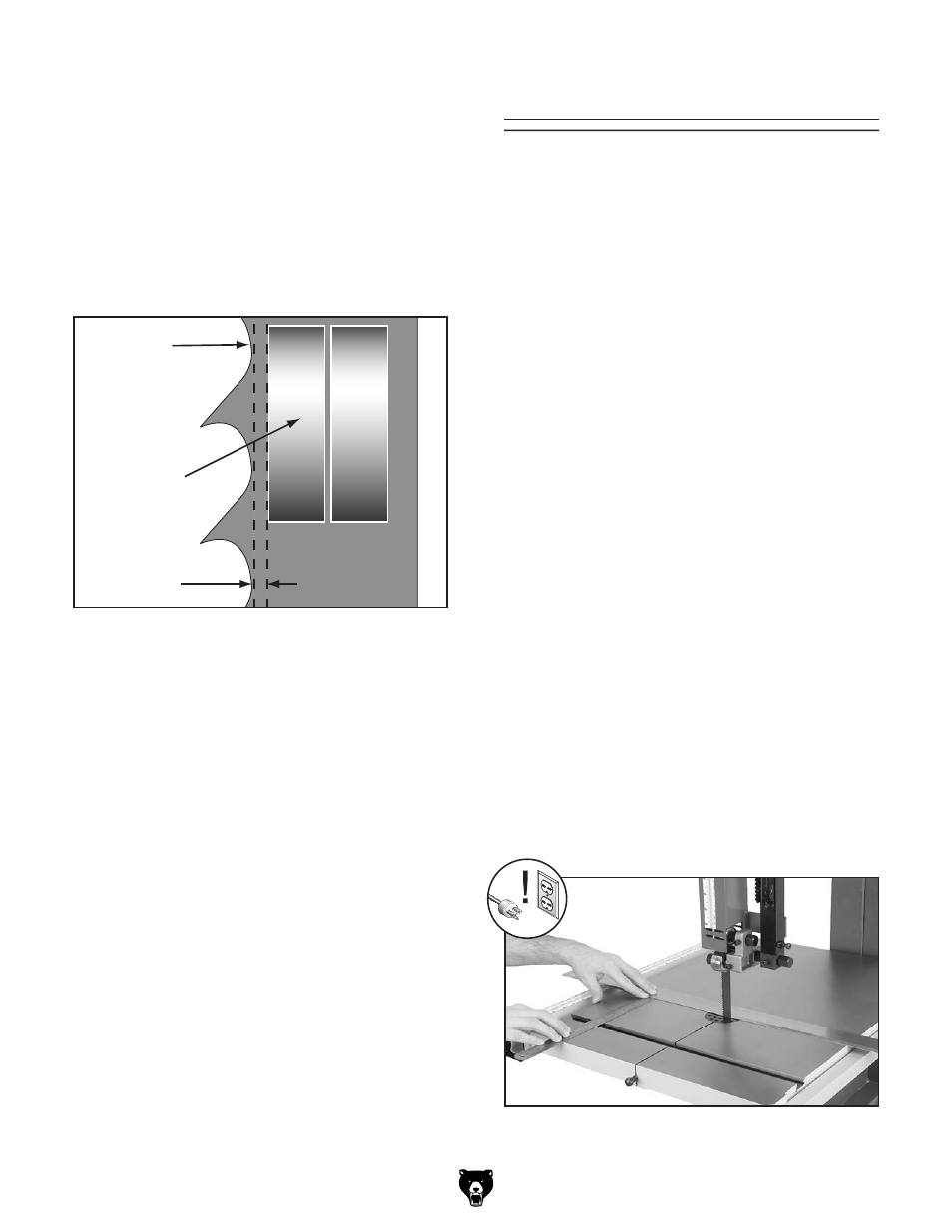
To align the table so the miter slot is parallel
to the bandsaw blade:
1. Make sure that the blade is tracking properly
and that it is correctly tensioned.
2. disCoNNECt BaNdsaW FroM poWEr!
3. loosen the trunnion bolts that secure the
table.
4. place an accurate straightedge along the
blade. the straightedge should lightly touch
both the front and back of the blade.
Note: Make sure the straightedge does not
go across a tooth.
5. use a fine ruler to gauge the distance
between the straightedge and the miter slot.
the distance you measure should be the
same at the front and the back of the table
(see
Figure 51).
Figure 51. Measuring for miter slot to be parallel
with blade.