Heating timing chart, Cooling timing chart, Ignition control diagnostic indicator chart – Goodman Mfg A/GPG13 M User Manual
Page 25
25
Light Signal
Refer to Abnormal Heating or Cooling Operation Sections of this Manual
Off
Internal Control Failure
1 Flash
External Lockout
2 Flashes
Pressure Switch Stuck Open
3 Flashes
Pressure Switch Stuck Closed
4 Flashes
Thermal Protection Device Open
5 Flashes
Flame Detected with Gas Valve Closed
6 Flashes
Short Cycle Compressor Delay (Cooling Only)
IGNITION CONTROL DIAGNOSTIC INDICATOR CHART
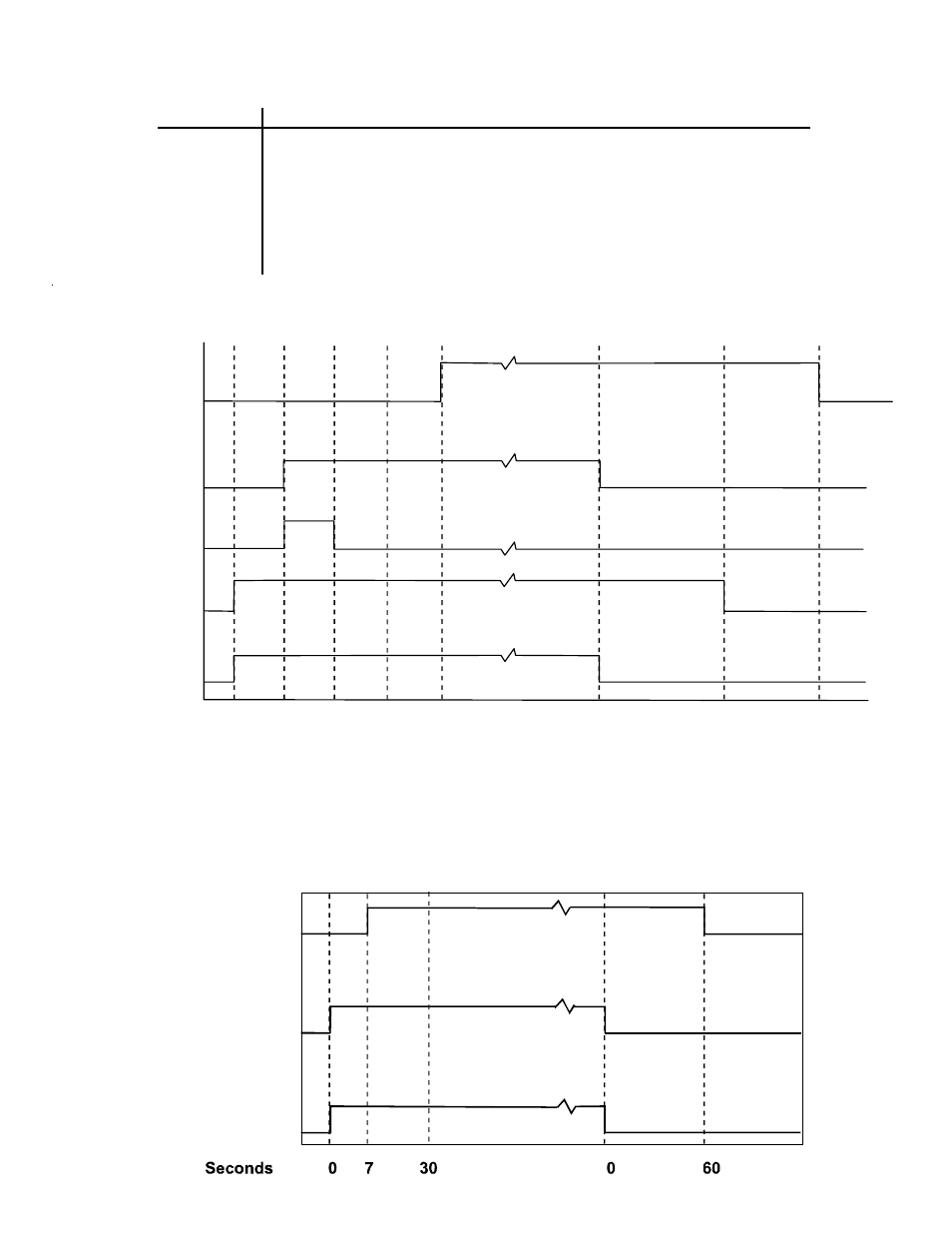
0 15 22 45 52 0 29 120, 135,150
Seconds
Gas Valve
Igniter
Thermostat
100 %
Circulator
Blower
Induced
Draft
Blower
HEATING TIMING CHART
Circulator
Blower
Outdoor Fan
and
Compressor
Thermostat
ON
OFF
ON
OFF
ON
OFF
COOLING TIMING CHART
ON
OFF
ON
OFF
ON
OFF
ON
OFF
OFF
100%