Inlet outlet, Warning, Caution – Goodman Mfg A/GPG13 M User Manual
Page 12
12
WARNING
T
O AVOID PROPERTY DAMAGE, PERSONAL INJURY OR DEATH DUE TO FIRE
OR EXPLOSION, A QUALIFIED SERVICER MUST INVESTIGATE THE REASON FOR
THE ROLLOUT PROTECTION DEVICE TO OPEN BEFORE MANUALLY RESETTING
THE ROLLOUT PROTECTION DEVICE.
Rollout Protection
Rollout Protection on Burner Bracket
Secondary Limit Control
The secondary limit control is located on the top of the blower
scroll assembly. This control opens when elevated
temperatures are sensed. Elevated temperatures at the
control are normally caused by blower failure. The reason for
the opening should be determined and repaired prior to
resetting.
If the power to the unit is interrupted during the heating cycle,
it may cause the secondary limit to trip. Once the blower
compartment temperature drops below the limit reset
temperature, the limit will automatically reset.
Secondary
Control Limit
Back of Unit
Secondary Limit Control
Pre-Operation Checks
1. Close the manual gas valve external to the unit.
2. Turn off the electrical power supply to the unit.
3. Set the room thermostat to its lowest possible setting.
4. Remove the heat exchanger door on the side of the unit by
removing screws.
5. This unit is equipped with an ignition device which
automatically lights the main burner. DO NOT try to light
burner by any other method.
6. Move the gas control valve switch to the OFF position. Do
not force.
7. Wait five minutes to clear out any gas.
8. Smell for gas, including near the ground. This is important
because some types of gas are heavier than air. If you
have waited five minutes and you do smell gas,
immediately follow the warnings on page 3 of this manual.
If having waited for five minutes and no gas smell is noted,
move the gas control valve switch to the ON position.
9. Replace the heat exchanger door on the side of the unit.
10. Open the manual gas valve external to the unit.
11. Turn on the electrical power supply to the unit.
12. Set the thermostat to desired setting.
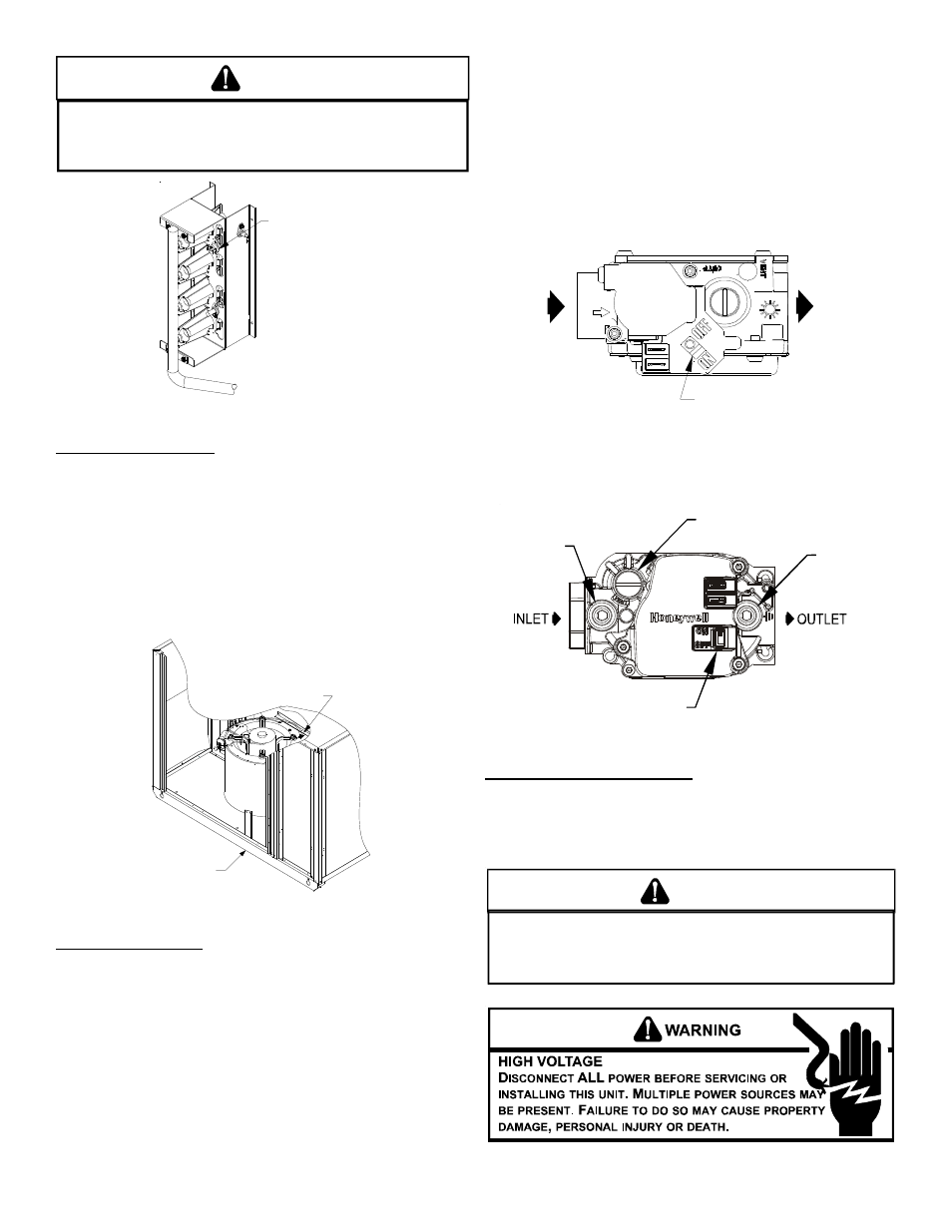
Gas Valve
On/Off
Selector
Switch
INLET
OUTLET
White-Rodgers 36G22
Gas Valve On/Off
Selector Switch
Inlet
Pressure
Tap
Pressure Regulator
(under cap screw)
Outlet
Pressure
Tap
Honeywell Model VR8215 (Single-Stage)
Gas Supply And Manifold Check
Gas supply pressure and manifold pressure with the burners
operating must be as specified on the rating plate.
G
AS
S
UPPLY
P
RESSURE
M
EASUREMENT
T
O
PREVENT
UNRELIABLE
OPERATION
OR
EQUIPMENT
DAMAGE
,
THE
I
NLET
GAS
SUPPLY
PRESSURE
MUST
BE
AS
SPECIFIED
ON
THE
UNIT
RATING
PLATE
WITH
ALL
OTHER
HOUSEHOLD
GAS
FIRED
APPLIANCES
OPERATING
.
CAUTION