Troubleshooting i, Warning – Goodman Mfg A/GPG13 M User Manual
Page 15
15
Adjust the thermostat setting below room temperature.
1. Main burners must go OFF.
2. Circulating Air Blower will continue to run for 120, 135 or
150 seconds, depending on the setting.
1
2
3
10
11
12
9
6
23
6
5
8
9
11
12
L2
L2
L2
L2
D1
L1
L
1
UNU
S
E
D
HE
A
T
CO
O
L
FS
K2
K1
R8
R10
R3
K4
K3
R31
LED
1068-83-400A
C27
D3
R38
D9
D10
R34
R35
R4
R11
R42
D12
R36
D11
D14
C20
Z1
R29
R22
C13
R25
D5
D7
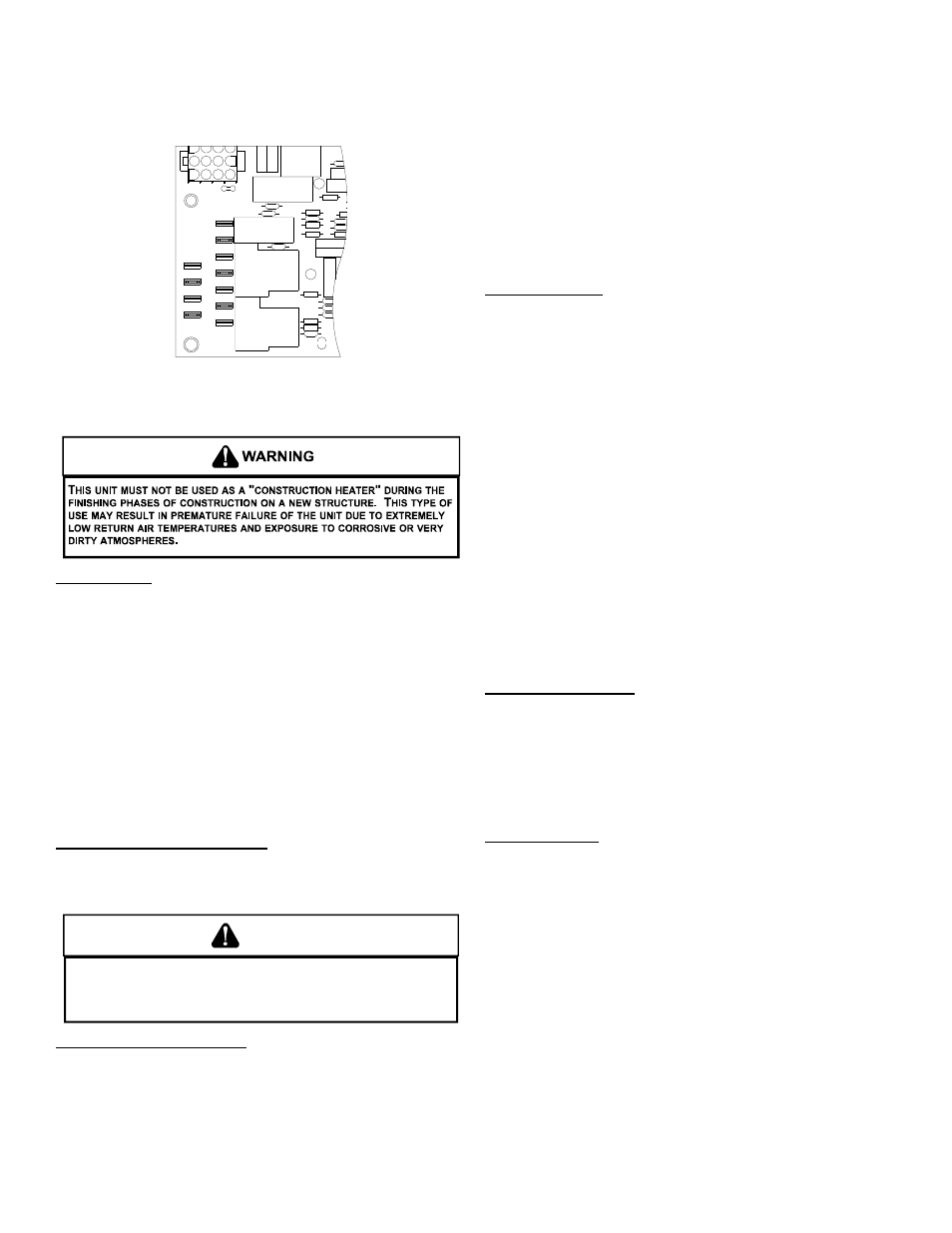
Control Board (Top)
NOTE: If necessary, adjust fan OFF delay settings to obtain satis-
factory comfort level.
Unit Shutdown
1. Set the thermostat to lowest setting.
2. Turn off the electrical power supply to the unit.
3. Remove the heat exchanger door on the side of the unit by
removing screws.
4. Move the gas control valve switch to the OFF position. Do
not force.
5. Close manual gas shutoff valve external to the unit.
6. Replace the heat exchanger door on the unit.
7. If cooling and/or air circulation will be desired, turn ON the
electrical power.
C
OOLING
S
TARTUP
NOTE: Check all manual reset limit controls in heating circuit if
cooling mode does not operate.
Compressor Protection Devices
The compressor includes components which are designed
to protect the compressor against abnormal operating
conditions.
WARNING
T
O PREVENT PERSONAL INJURY OR DEATH, ALWAYS DISCONNECT ELECTRICAL
POWER BEFORE INSPECTING OR SERVICING THE UNIT.
A
LL COMPRESSOR
PROTECTION DEVICES RESET AUTOMATICALLY, ENERGIZING THE CONTACTOR
AND OUTDOOR FAN.
Cooling Refrigerant Charging
Check unit charge before putting the cooling section into full
operation. The unit is factory charged with R-410A for nominal
air flow and static pressure conditions. The unit has a piston
flowrator expansion device.
To ensure the unit is properly charged for the intended
application, check the unit refrigerant superheat at the
compressor. The refrigerant superheat is a function of outdoor
ambient temperature and return air temperature of the
conditioned space. It is the installing contractors responsibility
to ensure the proper refrigerant superheat at the compressor
is adjusted for each application. For example, 10 degree
refrigerant superheat level is adequate for a 95 degree outdoor
ambient temperature and a 78 - 80 degree for indoor return
air temperature. As the outdoor ambient temperature rises
the superheat decreases and as the outdoor ambient
temperature lowers the superheat increases. Proper
superheat adjustment optimizes cooling performance.
Cooling Operation
NOTE: Mechanical cooling cannot be reliably provided at ambient
temperatures below 50° F.
1. Turn on the electrical power supply to the unit.
2. Place the room thermostat selector switch in the COOL
position (or AUTO if available, and if automatic changeover
from cooling to heating is desired).
3. Set the room thermostat to the desired temperature.
TROUBLESHOOTING
I
GNITION
C
ONTROL
E
RROR
C
ODES
The following presents probable causes of questionable unit
operation. Refer to Diagnostic Indicator Chart for an
interpretation of the signal and to this section for an explanation.
Remove the control box access panel and note the number of
diagnostic LED flashes. Refer to Diagnostic Indicator Chart
for an interpretation of the signal and to this section for an
explanation.
A
BNORMAL
O
PERATION
- H
EATING
Internal Control Failure
If the integrated ignition control in this unit encounters an
internal fault, it will go into a “hard” lockout and turn off the
diagnostic LED. If diagnostic LED indicates an internal fault,
check power supply to unit for proper voltage, check all fuses,
circuit breakers and wiring. Disconnect electric power for five
seconds. If LED remains off after restoring power, replace
control.
External Lockout
An external lockout occurs if the integrated ignition control
determines that a measurable combustion cannot be
established within three (3) consecutive ignition attempts. If
flame is not established within the seven (7) second trial for
ignition, the gas valve is de-energized, 15 second inter-purge
cycle is completed, and ignition is reattempted. The control
will repeat this routine three times if a measurable combustion
is not established. The control will then shut off the induced
draft blower and go into a lockout state.
If flame is established but lost, the control will energize the
circulator blower at the heat speed and then begin a new ignition
sequence. If flame is established then lost on subsequent
attempts, the control will recycle for four (4) consecutive
ignition attempts (five attempts total) before locking out.