Communications – GE GEK 106168E User Manual
Page 38
6. ACCEPTANCE TESTS
GEK-106168E
DBF Breaker Failure Protection
31
8.
Remove the current from terminals A1-A2. Remove voltage from digital input CC1.
9.
Repeat these steps with minimum and maximum voltages depending on the range of the relay.
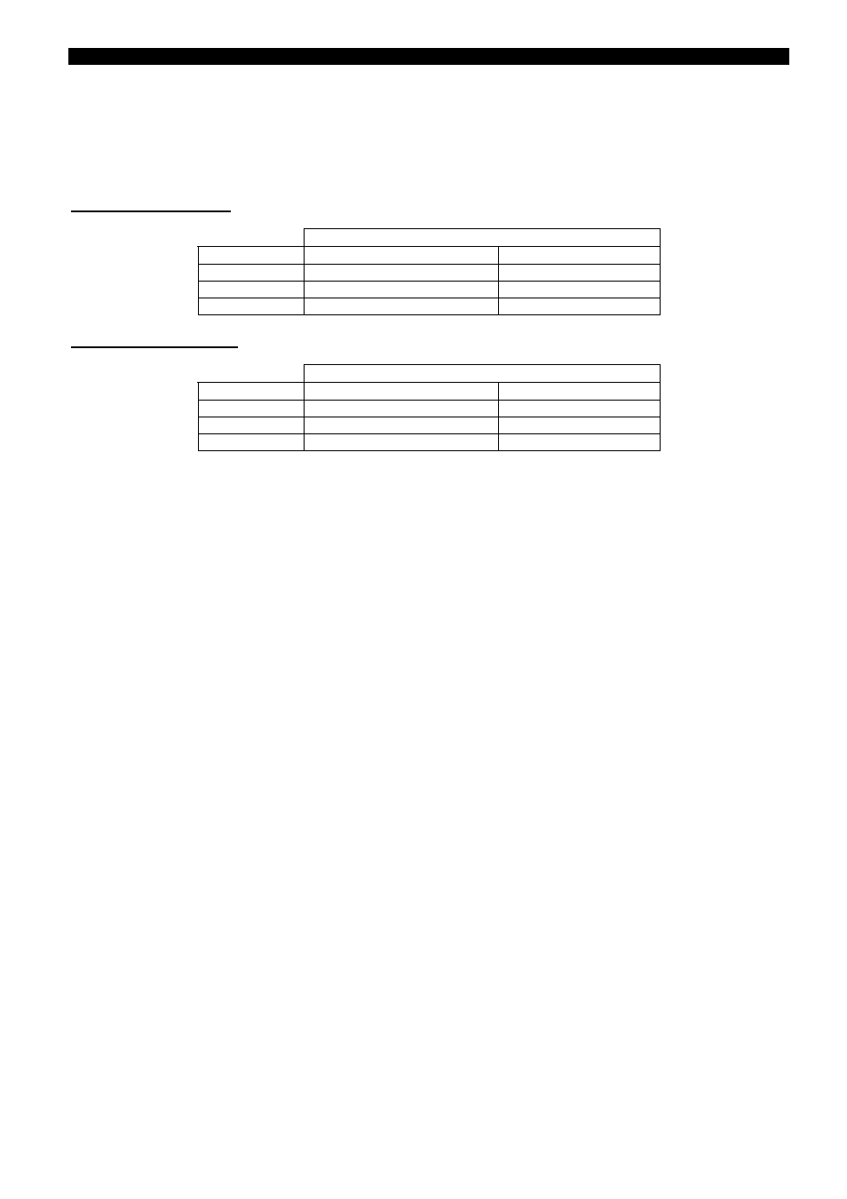
Test voltages and typical burdens are listed below:
Model "G" (48/125 VDC)
DC Battery (mA)
Voltage (Vdc)
Without Expansion Board
With expansion Board
38
340
440
125
250
320
150
225
300
Model "H" (110/250 VDC)
DC Battery (mA)
Voltage (Vdc)
Without Expansion Board
With expansion Board
88
300
370
110
250
320
300
150
220
6.7. COMMUNICATIONS
The object of this test is to check the communication ports of the relay (PORT1, PORT2 and PORT3). To do this
it is necessary to use a computer and the communications software GE_LOCAL. Figure 7 shows the series cable
and connection accessories necessary to establish the connection between the PC and the relay. Figure 8 shows
the cable and connectors necessary for remote connection (by MODEM) through PORT3.
The PC communication parameters necessary to match the relay default setting parameters are:
Relay number:
1
Remote port speed:
19200
Local port speed:
19200
Remote stop bit:
1
Local stop bit:
1
By using GE_Local communications software establish the connection and check that the relay communicates
through the three communication ports. Repeat this test with different baud rates and different power supply
voltages.