Relay setting, Indicators, Power supply – GE GEK 106168E User Manual
Page 37
6. ACCEPTANCE TESTS
30
DBF Breaker Failure Protection
GEK-106168E
6.4. RELAY SETTING
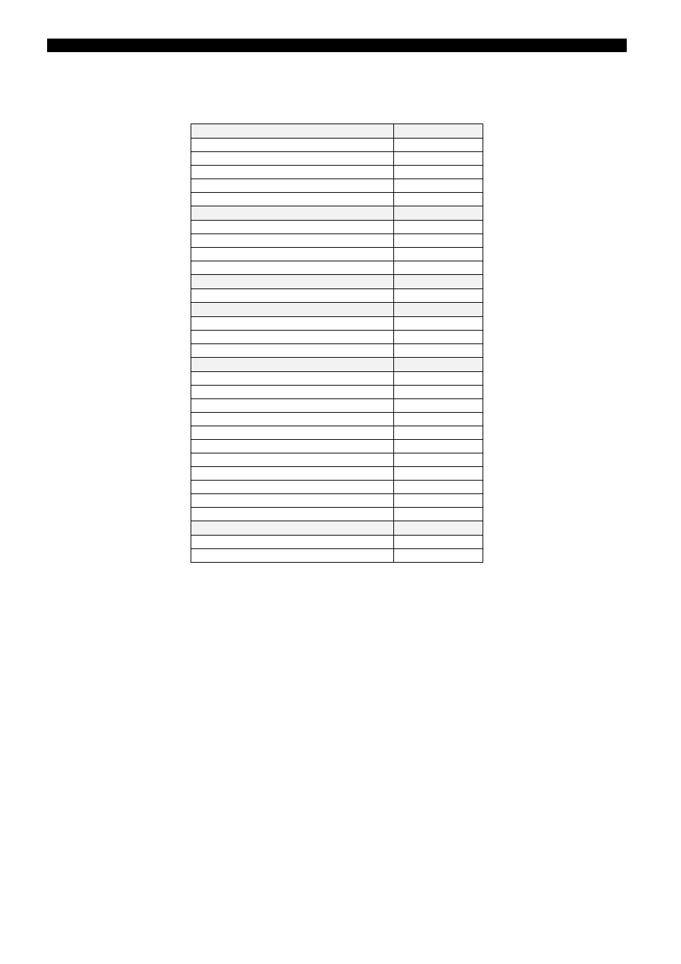
Introduce the following settings in the relay (by means of HMI or GE_Local software):
General Settings Group
Value
Relay Status
IN SERV
Identification
N/A
Frequency
50 Hz / 60 Hz
Phase CT Ratio
1
Neutral CT Ratio
1
Breaker Settings
Value
Breaker Number
N/A
KI2t Op. Mode
Fixed
KI2t INT. Time
0.06s
KI2t LIMIT
99999
Active Table Set
Value
Active Table
1
Function Permit
Value
50BF 1P Function
No Per
50BF 3P Function
No Per
3P NO INT Funct
No Per
50BF Settings Table 1
Value
PH Hiset Pickup
2A
PH Loset Pickup
1A
Neutral Pickup
1A
1 Phase Timer T1
1s
3 Phase Timer T2
1s
3P No I Timer T3
2s
BF Logic (3p/2P)
2 PHASE
Severe Fault 3P
Per
Low Load 2P
No Per
Nº Output Stages
1
2
nd
Stage Timer
2s
Internal Arc Settings Table 1
Value
Int Arc Pickup
1A
Int Arc Timer
1s
The specific settings required for each test are indicated; other settings do not affect the tests.
6.5. INDICATORS
Check that pressing the TARGET RESET button (with relay fed with rated dc power supply) all target LEDs light
up.
6.6. POWER SUPPLY
The relay operates with a dc power supply within
±
20% of the rated value. Check that the READY target LED in
the front of the relay lights up showing green color.
1.
Apply dc rated voltage to terminals A10-B10
2.
Change setpoint FUNCTION PERMIT/50BF 1P FUNCTION to PERM.
3.
Apply 2A to terminals A1-A2.
4.
Energize digital input CC1 PHASE A BF INITIATE (C9-D10).
5.
Wait 1second.
6.
Check that the READY target LED in the front of the relay lights up showing green color.
7.
Check the dc burden (see table below)