Console port pin assignments, Wiring map for serial cable – Foundry Networks IRONPOINT 250 User Manual
Page 47
Cables
August 2007
© 2007 Foundry Networks, Inc.
B-3
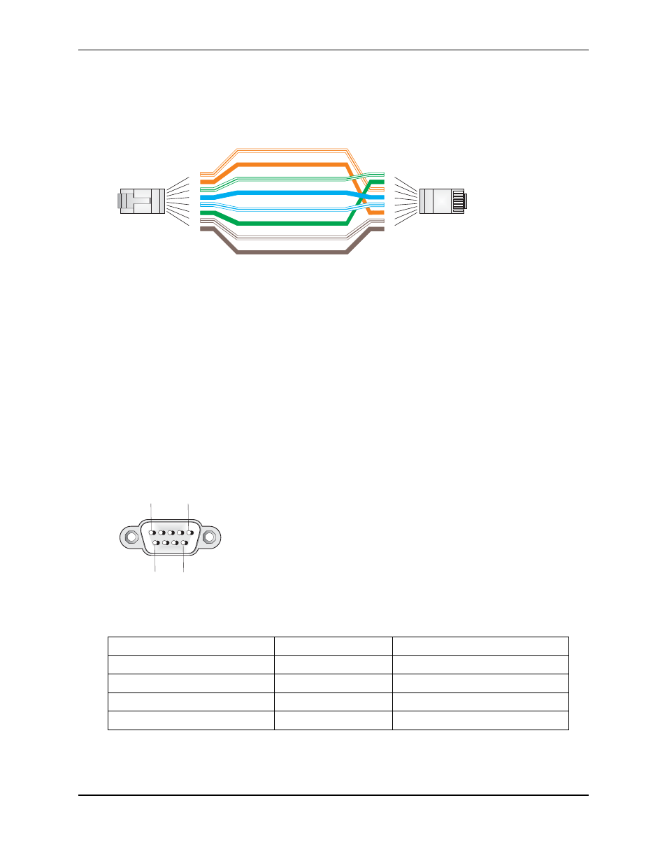
Figure B-3. Crossover Wiring
Console Port Pin Assignments
The DB-9 serial port on the IronPoint 250 is used to connect to the access point for out-of-band
management. The access point’s command-line interface can be accessed from a terminal or a PC
running a terminal emulation program.
Connect the console cable (included) to the RS-232 console port to access the command-line
interface. You can manage the access point using the console port, the Web interface, or SNMP
management software. Refer to the Foundry IronPoint Access Point User Guide for more
information.
The pin assignments used to connect to the console port are described in the following figure and
table.
Figure B-4. Serial Port (DB-9 DTE) Pin-Out
Wiring Map for Serial Cable
Signal (access point serial port)
Null Modem Cable
Signal (management console port)
2 RXD (receive data)
<---------RXD ------------
3 TXD (transmit data)
3 TXD (transmit data)
-----------TXD ---------->
2 RXD (receive data)
5 GND (ground)
-----------GND ----------
5 GND (ground)
1,4,6,7,8,9 Unused
1,4,6,7,8,9 Unused
Note: The left hand column pin assignments are for the male DB-9 connector on the access point. Pin 3
(TXD or “transmit data”) must emerge on the management console’s end of the connection as RXD
(“receive data”).
White/Orange Stripe
Orange
White/Green Stripe
1
2
3
4
5
6
7
8
1
2
3
4
5
6
7
8
EIA/TIA 568B RJ-45 Wiring Standard
10/100BASE-TX Crossover Cable
End A
End B
Green
Blue
White/Blue Stripe
Brown
White/Brown Stripe
1
5
6
9