Foundry Networks IRONPOINT 250 User Manual
Page 31
Installing the IronPoint 250 Access Point
August 2007
© 2007 Foundry Networks, Inc.
4-3
access point must be mounted with the RJ-45 cable connector oriented upwards to ensure proper
operation.
Do the following to attach the access point to the wall using the mounting bracket:
1. Using the mounting bracket, mark the position of the four screw holes on the wall. For concrete or
brick walls, you will need to drill holes and insert wall plugs for the screws.
2. Position the mounting bracket over the wall screw holes, then insert the included screws and
tighten them down to secure the bracket firmly to the wall. Use 5/8-inch number 12 wood screws
or a near equivalent (not included in the package contents).
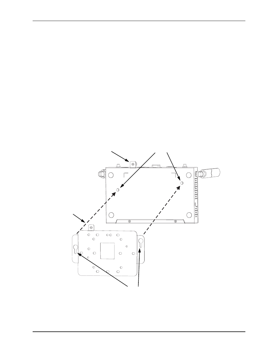
3. Attach the access point to the mounting bracket. Line up the two mounting points on the bracket
with the two mounting slots on the bottom of the access point (see the following figure). Place the
mounting points of the bracket into the mounting slots of the bracket, slide it into position so that
the bracket fastening screw on the access point lines up with the tab on the bracket. Then screw
down the fastening screw to secure the access point to the bracket.
Figure 4-2. Installing the Access Point on the Mounting Bracket
4. Position the antennas along the same axes. Each antenna emits a radiation pattern that is
toroidal (doughnut shaped), with the coverage extending most in the direction perpendicular to
the antenna. Therefore, the antennas should be oriented so that the radio coverage pattern fills
the intended service area. Also, the diversity antennas should both be positioned along the same
Mounting Points
Mounting Slots
Bracket
Fastening Screw
Align this tab with the
Fastening Screw