Powering up the access point, Powering up the access point -6 – Foundry Networks IRONPOINT 250 User Manual
Page 34
Foundry IronPoint 250 Installation Guide
4-6
© 2007 Foundry Networks, Inc.
August 2007
specific antenna and cable combinations. For this reason, you must consult with a professional
installer who is trained in RF installation and knowledgeable in the local regulations prior to
connecting an external antenna to your wireless radio product. It is the responsibility of the end user
to ensure that the antenna installation complies with the local radio regulations.
To install an external antenna:
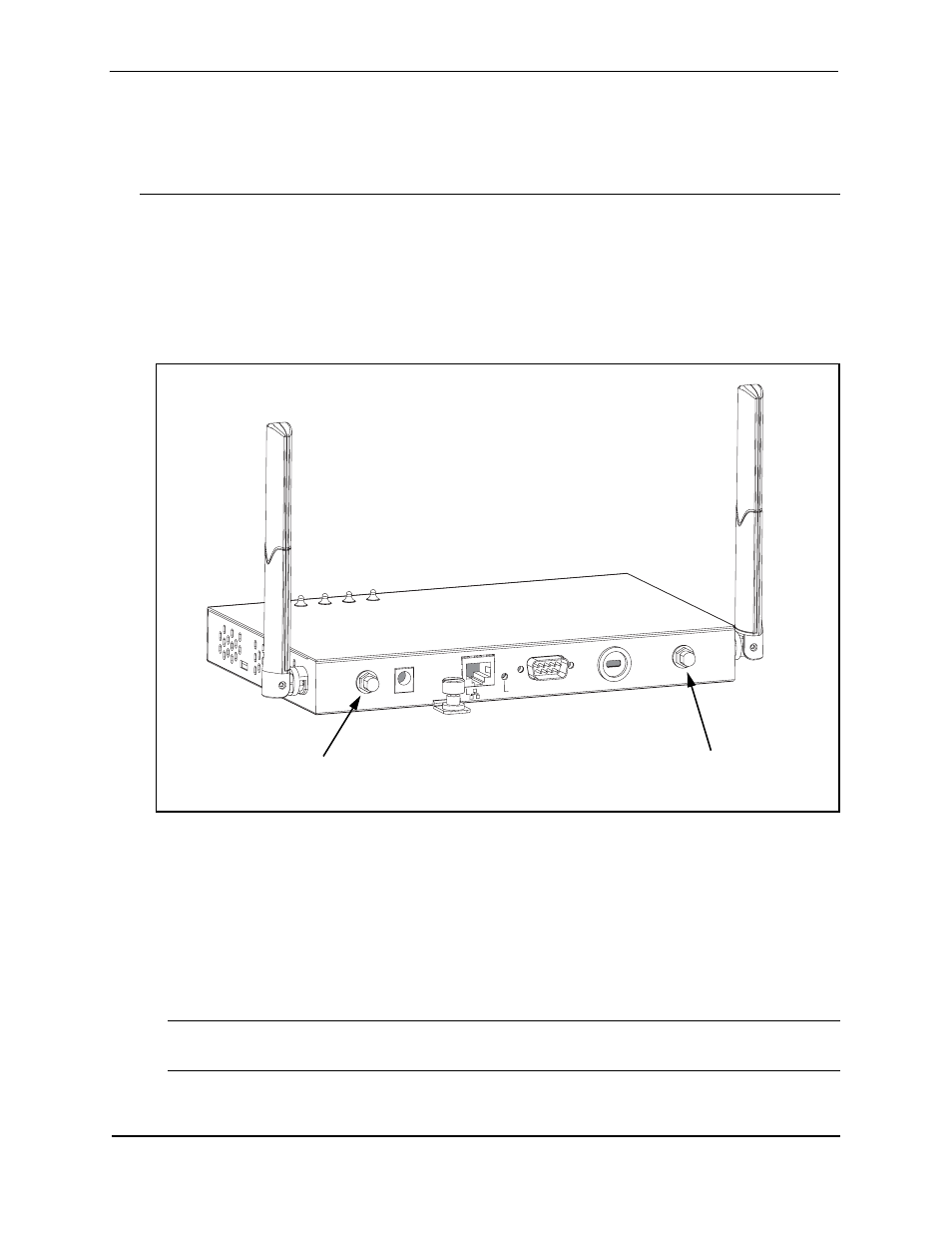
1. Connect the external antenna’s Reverse SMA connector to the access point’s external antenna
connector. Connect 2.4 GHz antennas to the connector labeled "802.11b/g" and 5.0 GHz
antennas to the connector labeled "802.11a."
Figure 4-5. Connecting the External Antenna
2. Set the Antenna Mode for the radio interface to "external" using the CLI or Web interface.
3. Enable the radio interface using the CLI or Web interface.
Powering Up the Access Point
Prepare the access point for power up by doing the following:
1. Connect the RS-232 console cable to the access point’s console port.
Note: The IronPoint access point also supports power over Ethernet (PoE) to obtain its power
from the RJ-45 port.
2. Connect the other end of the RS-232 console cable to your PC's serial port.
DC 48V / 0.38A
POE In
Reset
Console
Lock
802.11b/g
802.11a
External Antenna
Connector
(802.11b/g Radio)
External Antenna
Connector
(802.11a Radio)