Status leds, Status leds -5 – Foundry Networks IRONPOINT 250 User Manual
Page 21
About the IronPoint 250
August 2007
© 2007 Foundry Networks, Inc.
2-5
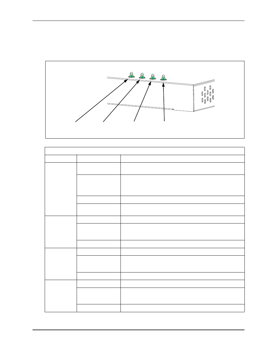
Status LEDs
The access point includes four status LED indicators, as described in the following figure and table.
Figure 2-3. Status LEDs
Status LEDs
LED
Status
Description
Status
On Green
Indicates that power is being supplied and the system is working
normally.
Flashing Green
Indicates -
• the access point is running its self-test
• the access point is loading a software file
On Amber
Indicates a CPU or system failure.
Flashing Amber
(Prolonged)
Indicates a system error.
Link
On Green
Indicates a valid 10/100 Mbps Ethernet cable link.
Flashing Green
Indicates that the access point is transmitting or receiving data on
the attached 10/100 Mbps Ethernet LAN. The flashing rate is
proportional to network activity.
Off
Indicates no 10/100 Mbps Ethernet cable link.
Radio a
On Green
Indicates the 802.11a radio is enabled.
Flashing Green
Indicates that the access point is transmitting or receiving data
through 802.11a wireless links. The flashing rate is proportional to
network activity.
Off
Indicates the 802.11a radio is disabled.
Radio b/g
On Green
Indicates the 802.11g radio is enabled.
Flashing Green
Indicates that the access point is transmitting or receiving data
through 802.11g or 802.11b wireless links. The flashing rate is
proportional to network activity.
Off
Indicates the 802.11g radio is disabled.
802.11a
Wireless
Link/Activity
Ethernet
Link/Activity
802.11b/g
Wireless
Link/Activity
Power