Tide vector, Display – Furuno CI-35H User Manual
Page 34
3-10
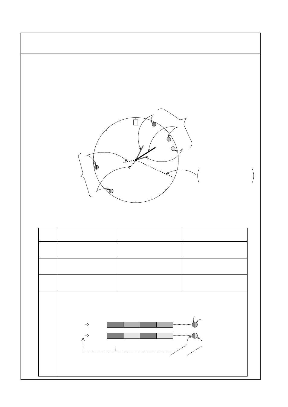
TIDE VECTOR/COURSE PLOT SECTION
TIDE VECTOR
Display
`
Each tide vector can be switched on and off independently by MENU 1 - “LAYER n” setting.
(Refer to page 4-2.)
`
Tide differential vectors can be switched on and off by MENU 1 - “TIDE DIF DISP” setting.
(Refer to page 4-2.)
`
Each vector bar indicates “flowing to” own ship direction with the standard factory setting. It is
possible to reverse the pointing direction to “flowing from.”
Note:
If vector bars of two or more layers point in the same direction, only the vector bar and the
direction mark of the shallowest layer appear.
N
W
E
S
Tide vectors
Heading line
Presented in North-up
mode only.
Tide differential
vectors.
1
2
3
4
5
Ground Tracking Mode
(See page 3-6)
Water Tracking Mode
(See page 3-6)
Nav-aided Mode
(See page 3-6)
1
(YEL)
2
(PPL)
3
(L-BLU)
Absolute tide movement
of layer 1
Absolute tide movement
of layer 2
Absolute tide movement
of layer 3
Relative tide movement of
layer 1 based on surface
layer.
Relative tide movement of
layer 2 based on surface
layer.
Relative tide movement of
layer 3 based on surface
layer.
Absolute tide movement of
layer 1 (nav-tide)
Absolute tide movement of
layer 2 (nav-tide)
Absolute tide movement of
layer 3 (nav-tide)
4
5
Tide differentials between a specified reference layer and the other two layers.
(Ex. Ref. Layer = #2)
2 1
2 3
PPL
YEL
PPL
YEL
PPL
LBLU
PPL
LBLU
PPL
LBLU
PPL
YEL
Ref. layer
(Left half)
Measuring layer
(Right half)
. . . . . . .
. . . . . . .