3 dvi-rgb conversion kit – Furuno FAR2167DS-BB User Manual
Page 68
4-13
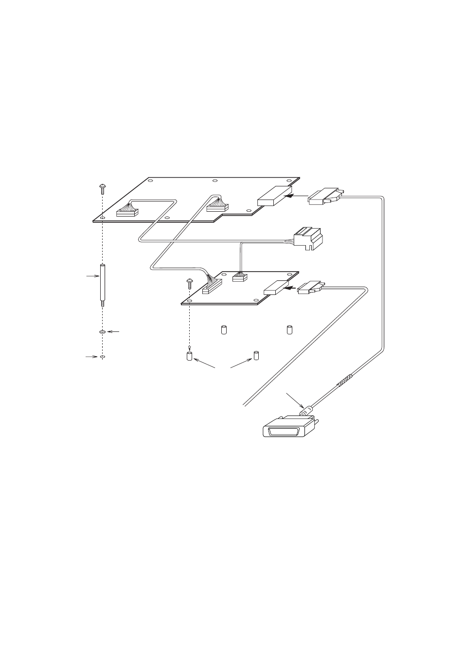
4.3 DVI-RGB Conversion Kit
This information provides the procedure necessary for the installation of the DVI-RGB conversion
kit. This kit is installed in the processor unit to enable connection of an RGB monitor or VDR
(Voyage Data Recorder).
Name:
DVI-RGB conversion kit
Type:
OP03-180-2
Code no.: 008-536-070
See packing list for contents. Refer to the figure below for modification.
How to wire the DVI-RBG conversion board
M3x8
4 pcs
Spacer
SQ-35
6 pcs
Fixing
holes
Spring washer
Boss
J2
J3
(3 pin)
J1
(13 pin)
J615
J3
J9
(10 pin)
J4
(6 pin)
M3x8
6 pcs
RGB Cable
(User supply)
Clamp copper tape
section by cable clamp.
Ferrite core side: Connect to DVI-D port on
the upper part of the processor unit.
DVI cable
03P9342 board
RGB-BUFF board
(03P9229B)
(SLB-FRN4-A)
DVI-RGB CONVERSION board
03-2092
03-2094
03-2093
Ferrite core
To external monitor or
BNC connector converter
(see page 4-15).
D-sub 15P
Female
- FAR-2805 Series (169 pages)
- FR-8062 (2 pages)
- FR-8122 (56 pages)
- CH-37 (90 pages)
- CH-37 (71 pages)
- FAR-2XX7 (4 pages)
- FAR-2XX7 (2 pages)
- FELCOM16 (4 pages)
- FRS-1000B (8 pages)
- FRS1000 (8 pages)
- Ls4100 (48 pages)
- 520 (73 pages)
- Marine Radar (24 pages)
- 1944C-BB (233 pages)
- 1733C (260 pages)
- FR-2105 (197 pages)
- FMD-8010 (50 pages)
- GD-1900C (260 pages)
- Black Box Video Sounder FCV-1200BB (2 pages)
- FR-1505 MARK-3 (4 pages)
- 1762 (252 pages)
- NAVnet DRS12A (44 pages)
- FAR-2137S (8 pages)
- FAR-2127 (136 pages)
- FA30 (6 pages)
- Satellite Compass SC-50/110 (30 pages)
- 1715 (2 pages)
- 1715 (48 pages)
- GD-1720C (53 pages)
- 1734C (55 pages)
- Mu 120c (2 pages)
- NAVNET GD-1920C (239 pages)
- CI-80 (41 pages)
- FAR-28x7 Series (299 pages)
- FAR-2837S (8 pages)
- BBWX1 (2 pages)
- 851 MARK-2 (37 pages)
- 851 MARK-2 (47 pages)
- BBFF3 (1 page)
- CSH-53 (108 pages)
- CSH-53 (106 pages)
- FCV295 (53 pages)
- FR1500 Mk3 (79 pages)
- FI-50 Series (2 pages)
- FCV-1150 (32 pages)