5 power supply unit, Mounting considerations, Mounting procedure – Furuno FAR2167DS-BB User Manual
Page 23
1-16
1.5 Power Supply Unit
Mounting considerations
The power supply unit may be mounted on a bulkhead or a deck. Because it has no operation
requirements it can be located almost anywhere, provided the location is well ventilated.
Mounting procedure
Fix the unit to the mounting location with four 6×20 self-tapping screws (local supply). For
mounting on a bulkhead, do the following:
1. Mark location for mounting holes.
2. Screw in the self-tapping screws at the location for the bottom fixing holes, leaving a gap of
about 5 mm between the bottom of the screw head and bulkhead.
3. Set the unit to the screws inserted at step 1.
4. Fasten the self-tapping screws at the top of the unit.
5. Tighten all self-tapping screws.
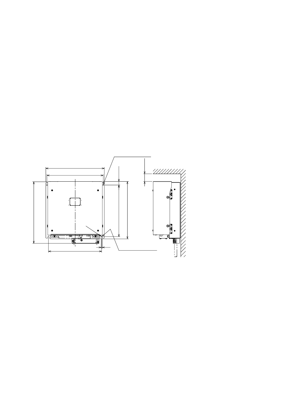
Mounting dimensions for power supply unit
25
340±1
380
385
410
350±1
2-
φ
7 FIXING HOLES
R3.5
370±1
7
2-FIXING NOTCH
#50
# Minimum recommended
service space
- FAR-2805 Series (169 pages)
- FR-8062 (2 pages)
- FR-8122 (56 pages)
- CH-37 (90 pages)
- CH-37 (71 pages)
- FAR-2XX7 (4 pages)
- FAR-2XX7 (2 pages)
- FELCOM16 (4 pages)
- FRS-1000B (8 pages)
- FRS1000 (8 pages)
- Ls4100 (48 pages)
- 520 (73 pages)
- Marine Radar (24 pages)
- 1944C-BB (233 pages)
- 1733C (260 pages)
- FR-2105 (197 pages)
- FMD-8010 (50 pages)
- GD-1900C (260 pages)
- Black Box Video Sounder FCV-1200BB (2 pages)
- FR-1505 MARK-3 (4 pages)
- 1762 (252 pages)
- NAVnet DRS12A (44 pages)
- FAR-2137S (8 pages)
- FAR-2127 (136 pages)
- FA30 (6 pages)
- Satellite Compass SC-50/110 (30 pages)
- 1715 (2 pages)
- 1715 (48 pages)
- 1734C (55 pages)
- GD-1720C (53 pages)
- Mu 120c (2 pages)
- NAVNET GD-1920C (239 pages)
- CI-80 (41 pages)
- FAR-28x7 Series (299 pages)
- FAR-2837S (8 pages)
- BBWX1 (2 pages)
- 851 MARK-2 (37 pages)
- 851 MARK-2 (47 pages)
- BBFF3 (1 page)
- CSH-53 (106 pages)
- CSH-53 (108 pages)
- FCV295 (53 pages)
- FR1500 Mk3 (79 pages)
- FI-50 Series (2 pages)
- FCV-1150 (32 pages)