Furuno 1935 User Manual
Page 23
1-17
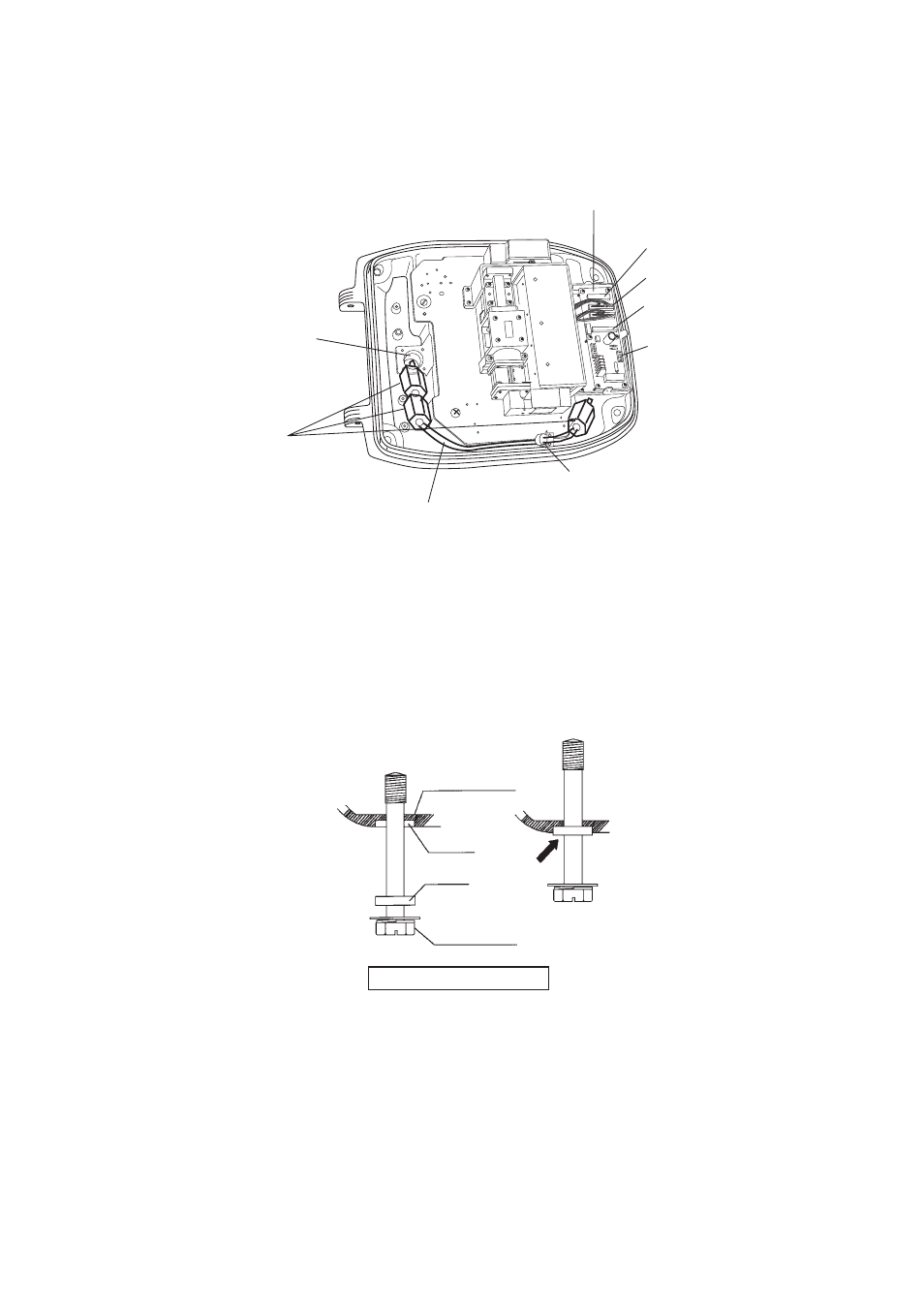
8. Connect the signal cable to the RTB Board (03P9249). See the interconnection diagram and
the figure shown below.
9. Attach three EMI cores to the signal cable as shown below.
Antenna unit chassis, cover opened
10.Fasten the signal cable with the cable clamp.
11.Undo the stay and close the cover. Securely fasten the scanner bolts.
Note: When you close the cover, set the gaskets to the grooves in the bottom chassis, then tighten
the bolts.
Run cable along here.
Lead in
cable here.
J821 VH9P
RTB Board
J824 NH13P
J823 VH4P
EMI core
RFC-13
Clamp
J822 VH2P
Bottom
Chassis
Gasket
Groove
Antenna Bolt
Torque : 9.8 ±0.1 Nm
See also other documents in the category Furuno Boating Accessories:
- 2817-D (136 pages)
- 841 MARK-2 (58 pages)
- FAR-2157-BB (111 pages)
- UAIS TRANSPONDER FA-150 (4 pages)
- NAVNET 1763C (260 pages)
- FR-1710 (78 pages)
- FAR-2807 (52 pages)
- MARINERADAR FR-8062 (56 pages)
- FR-7062 (52 pages)
- FR-7252 (48 pages)
- COLOR VIDEO PLOTTER 1943C (251 pages)
- NAVPILOT 520 (73 pages)
- FAR-2167DS (111 pages)
- NAVpilot NAVpilot-500 (73 pages)
- FAR-2827 (135 pages)
- NAVNET 1823C (260 pages)
- FR-2155 (89 pages)
- FA-100 (58 pages)
- NAVNET 1943 (248 pages)
- 1622 (24 pages)
- FR-2115/2125 (79 pages)
- 1942 MARK-2 (52 pages)
- 1942 MARK-2 (46 pages)
- 2137S (123 pages)
- 1832 (62 pages)
- 1832 (64 pages)
- 1832 (63 pages)
- FAR-2167DS-D (111 pages)
- 821 (64 pages)
- FR-8251 (69 pages)
- FR-2135S (82 pages)
- FAR-2127-BB (136 pages)
- NX-700A/B (89 pages)
- MSC.36(63) (1 page)
- IF-1500AIS (12 pages)
- FR-8051 (64 pages)
- FAR-2157 (111 pages)
- FAR-2157 (8 pages)
- 1712 (27 pages)
- UAIS TRANPONDER FA-150 (128 pages)
- FAR-2107(-BB) (312 pages)
- NATVET 1824C (239 pages)
- FAR-2107 (280 pages)
- NAVPILOT 500 (73 pages)