5 power requirements, 5 operating switches – Frymaster FLYMASTER KSCFH18E User Manual
Page 15
KSCFH18E COOL ZONE SERIES ELECTRIC FRYERS
CHAPTER 3: INSTALLATION INSTRUCTIONS
3-4
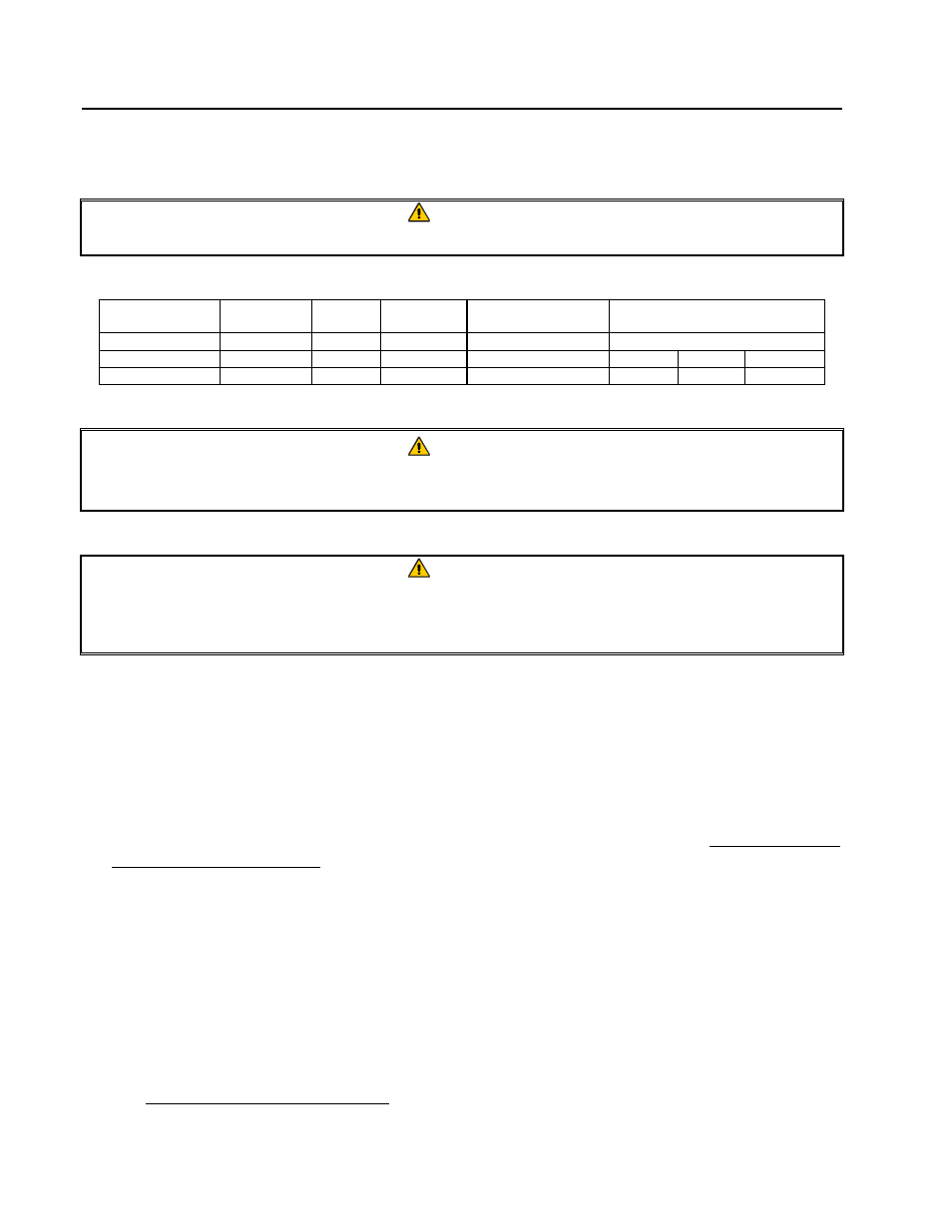
3.5 Power Requirements
DANGER
Copper wire suitable for at least 167°F (75°C)
MUST be used for power connections.
MODEL
VOLTAGE
PHASE
WIRE
SERVICE
MIN.
AWG
SIZE
(mm
2
)
AMPS PER LEG
L1
L2
L3
KSCFH18E
208
3
3
6
(16)
50
50
50
KSCFH18E
240
3
3
6
(16)
43
43
43
DANGER
The electrical power supply for this appliance
MUST be the same as indicated on
the rating plate located on the inside of the fryer door.
DANGER
All wiring connections for this appliance
MUST be made in accordance with the
wiring diagrams furnished with the equipment. Wiring diagrams are located on the
inside of the fryer door.
3.5 Operating Switches
A. Fryer with KFC-1 Computer
This fryer/filter system is equipped with a drain valve safety switch and a frypot float-switch on
each of the two-batteried fryers. Drain-valve safety switches de-energize the fryer heating
elements during the filter process, thus providing an additional safety feature. Always leave the
computer on when filtering.
The KFC-1 computer monitors filter operations. The computer logs the number of times the
fryer has been filtered, and will lock out when a preset number is reached. The drain valve must
be opened and closed, and the frypot refilled with oil/shortening before the KFC-1 computer will
allow a cook cycle (after filtering).
See the KFC-1 Computer User’s Manual for detailed information.
B. Other Fryer/Filter Switches
1. Fryer Power Switch (Computer): The fryer’s power is turned on and off with the computer.
See computer manual for more detail.