Festool 1400 EQ User Manual
Page 10
10
Milling cutters
Do not exceed the maximum speed specified on
the tool and/or keep to the speed range. Cracked or distorted
cutters must not be used.
You can turn the machine upside down when changing the
tool.
Inserting the tool
- Insert the router (5.3) into the open clamping collet as far as
possible, but at least up to the mark
on the router shank.
- Press the switch (5.1) for locking the spindle on the right-
hand side.
- Tighten the locking nut (5.2) with a 19 mm open-end spanner.
Removing the tool
- Press the switch (5.1) for locking the spindle on the left-
hand side.
- Undo the nut (5.2) using an open-end wrench (SW 19) until
you are able to remove the tool.
Note: the spindle lock only blocks the motor spindle in one
direction of rotation at any one time. Therefore when the nut
is undone or tightened, the wrench does not need to be offset
but can be moved back and forth like a ratchet.
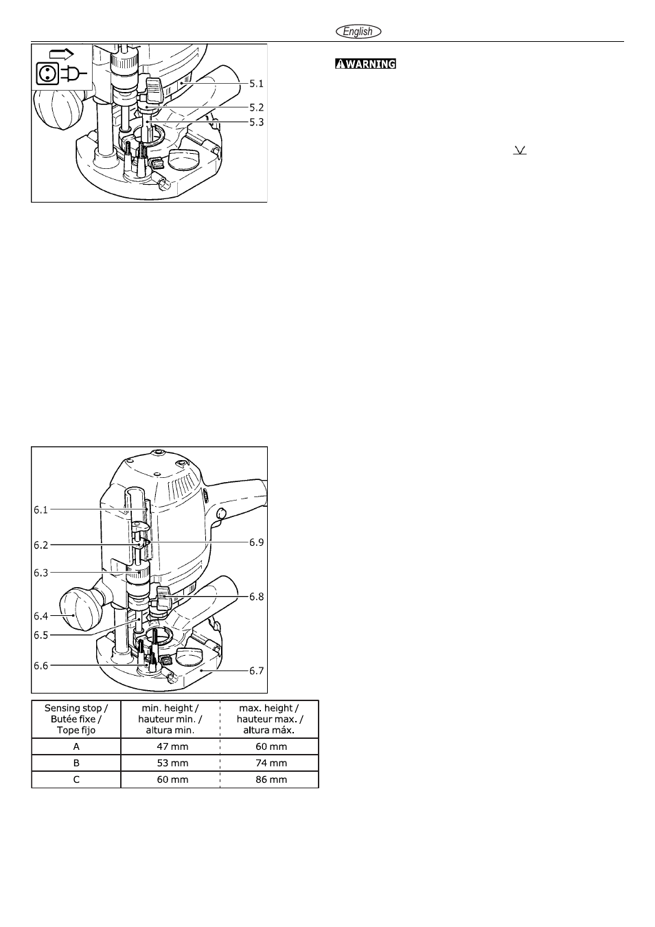
Adjusting the milling depth
The milling depth is adjusted in three stages:
a) Setting the zero point
- Open the clamping lever (6.8) so that the stop cylinder (6.5)
can move freely.
- Place the router with router table (6.7) onto a smooth surface.
Open the rotary knob (6.4) and press the machine down
until the milling cutter rests on the base. Clamp the machine
tight in this position with the rotary knob (6.4).
- Press the stop cylinder against one of the three sensing stops
of the pivoted turret stop (6.6).
- The individual height of each sensing stop (see table beside)
can be adjusted with a screwdriver.
- Push the pointer (6.2) down so that it shows 0 mm on the
scale (6.1).
If the base position is incorrect, this can be adjusted with the
screw (6.9) on the indicator.
b) Setting the milling depth
The desired milling depth can be set either with the quick
depth adjustment or with the fine depth adjustment.
- Quick depth adjustment: Pull the stop cylinder (6.5) up
until the pointer shows the desired milling depth. Clamp the
stop cylinder in this position with the clamping lever (6.8).
- Fine depth adjustment: Clamp the stop cylinder with the
clamping lever (6.8). Set the desired milling depth by turning
the adjusting wheel (6.3) in. Turn the adjusting wheel to the
next mark on the scale to adjust the milling depth by 0.1 mm.
One full turn adjusts the milling depth by 1 mm. The maximum
adjustment range with the adjusting wheel is 8 mm.
c) Increasing the milling depth
- Open the rotary knob (6.4) and press the tool down until the
stop cylinder touches the sensing stops.
- Clamp the machine in this position by tightening the rotary
knob (6.4).
Clamping collet changing
- Press the switch (5.1) for locking the spindle on the left-
hand side. Fully unscrew the nut (5.2) and remove from
spindle together with the clamping collet.
- Press the switch (5.1) for locking the spindle on the right-
hand side. Insert a new clamping collet with nut into the
spindle and slightly tighten the nut. Do not tighten the nut
until a milling cutter has been fitted.