Installation instructions, Wiring diagram – Fisher & Paykel OR60 User Manual
Page 21
19
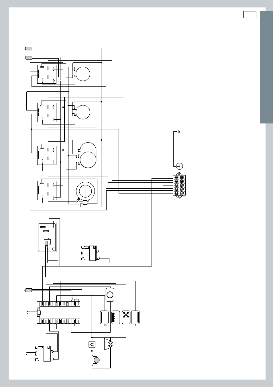
Wiring
diagram
CER
AMIC GLASS C
OOK
T
OP MODELS
Installation instructions
M
S2
T
F2
F4
F3
F5
P3
P4
P2
P1
PR
TS
CR
TL
S1
F1
C
G
S
V
CIR
TM
CF
LF
5
4
3
2
1
H
H
SS
22
44
S1
S1
S1
S1
S2
S2
S2
S2
44
44
P1
P1
P1
P1
P2
P2
P2
P2
PILOT
22
22
4A
H
S
2
4
4
4A
H
S
2
4a
4a
PILOT
N/7
1
1a
L/8
1
6
1a
6a
4
9
4a
9a
3
8
3a
8a
2
7
2a
7a
5
10
11
5a
10a
11
a
ELECTRIC DIAGRAM KEY
F1
F4/5
F2/3
LF
TM
TS
PR
C
G
S
V
CIR
CR
S1
S2
P3/4
P1/2
M
T
CF
TL
Oven switch
Energy regulators (single zones)
Energy regulators (double zones)
Oven lamp
Oven thermostat
Safety thermostat
Electronic programmer
T
op heating element
Grill heating element
Bottom heating element
Fan motor
Circular heating element
Residual heat lamp
Thermostat pilot lamp
Radiant heaters pilot lamp
Single zone radiant heaters
Double zone radiant heaters
T
e
rminal block
Earth connection
Cooling fan motor
Thermal overload