Installation instructions, Important – Fisher & Paykel OR60 User Manual
Page 10
8
Installation instructions
FOUR FUNC
TION MODELS
GAS C
OOK
T
OP MODELS
365
235
600 mm
min 105
max 120
0
+ 15
+ 15
(Cavity width)
1
2
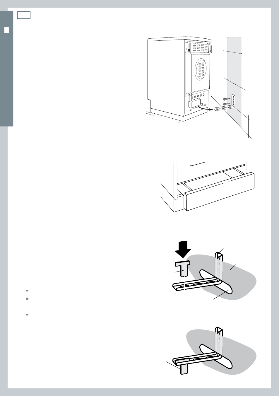
Fitting the anti-tilt bracket
(four-function models)
Important!
To restrain the appliance and prevent it tipping
accidentally, fit a bracket to its rear to fix it
securely to the wall. Make sure you also fit the
supplied lock pin to the anti-tiit bracket.
To fit the anti-tilt bracket:
1
After you have located where the cooker
is to be positioned, mark on the wall the
place where the two screws of the anti-tilt
bracket have to be fitted. Please follow the
indications given in Fig.5a.
2
Drill two 8 mm diameter holes in the wall
and insert the plastic plugs supplied.
Important!
Before drilling the holes, check that you will not
damage any pipes or electrical wires.
3
Loosely attach the anti-tilt bracket with the
two screws supplied.
4
Move the cooker to the wall and adjust the
height of the anti-tilt bracket so that it can
engage in the slot on the cooker’s back, as
shown in Fig.5a.
5
Tighten the screws attaching the anti-tilt
bracket.
6
Push the cooker against the wall so that the
anti-tilt bracket is fully inserted in the slot
on the cooker’s back.
7
Access the bracket and fit the lock pin;
Remove the drawer (Fig. 5b).
Fit the lock pin through the bracket,
as shown (Fig.5c).
Refit the drawer.
Fig. 5c Fitting the lock pin through the bracket
Anti-tilt bracket
attached on the
rear wall
Cooker’s
back
Lock pin
Slot on the
cooker’s back
Lock pin
correctly fi tted
Fig. 5b Removing the drawer
Fig. 5a Fitting the anti-tilt bracket