Figure 2, Figure 1, Assembly instructions – Fitness Quest Quest Ab Lounge XL System User Manual
Page 7
--------
5
--------
ASSEMBLY INSTRUCTIONS
Step 1.
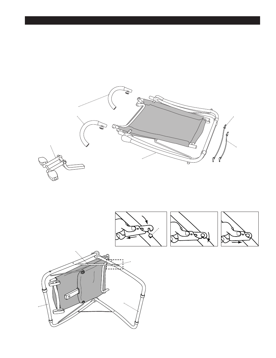
Remove the Main Assembly and all parts from packing
and place them on floor as shown in Figure 1.
Occasionally our products contain components that are pre-lubricated at the factory. We recommend
that you protect flooring, or anything else the parts may contact, with newspaper or cloth.
FIGURE 2
X15901-2
Rear Frame
X15901-1
Front
Frame
X15901-8
Locking Arm
Step 2. Lift and place the unit on its
right side with the left side and Locking
Arm facing up as shown in Figure 2.
Open the unit by grasping the bottom of
the Front and Rear Frames and spread
them apart.
Swing the Locking Arm, located on the
Left Front Frame, around so the notch
lines up with the pin on the Left Rear
Frame. Push down on the button on
the Locking Arm Mechanism and slide
it back while you hook the notch over
the pin.
X15901
Main Assembly
FIGURE 1
X15908-7
Long Band
X15908-8
Short Band
X15908-1
Handlebar with Locking Knob
X15901-8
Locking Arm
Mechanism
X15906
Foot Rest Assembly
Pin
Attaching the Locking Arm Mechanism
NOTE: All location references, such as front, rear, left
or right, made in these instructions are from the user
sitting on the unit and facing forward.