Configuration diagram primergy rx600 s3 – Fujitsu Siemens Computers RX600 S3 User Manual
Page 3
System configurator and order-information guide
PRIMERGY RX600 S3 Status 2007-01-24
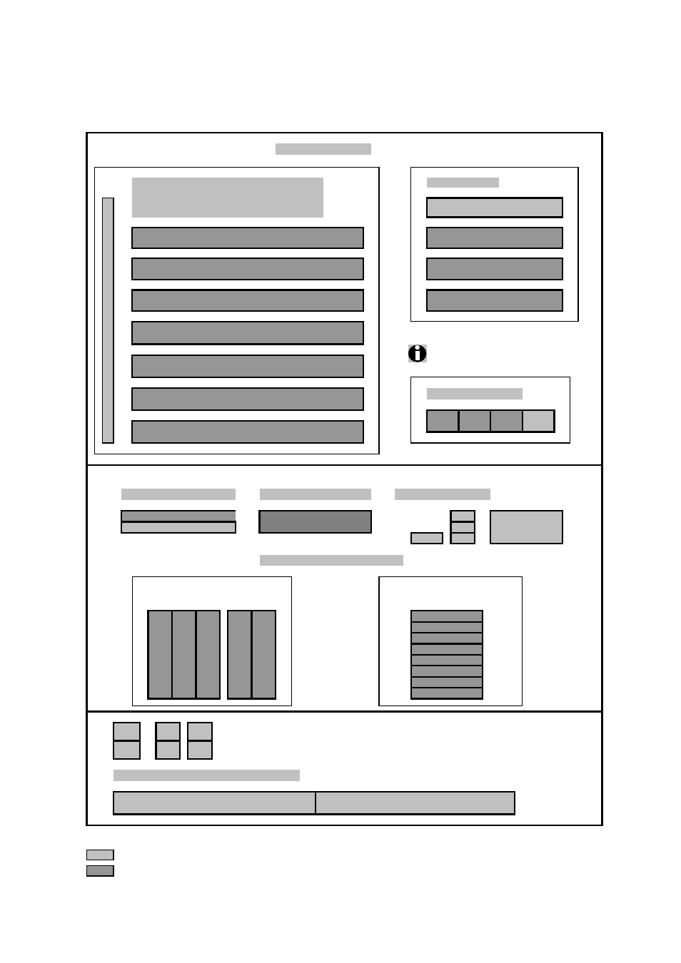
Configuration diagram PRIMERGY RX600 S3
TOP View
System unit ( I )
Extension slots
Memory ( III )
SCSI / RAID controller ( VIII )
Fiber Channel ( IX )
Communication/Network ( X )
7
6
5
4
Processors must be plugged
in order according the picture.
3
Processor ( II )
2
1
FRONT VIEW
Accessible drives
Tape drives ( VII )
Operating Panel
5.25"x 0.5" bay for CD/DVD
Local View LCD Display
Hard disk drives ( IV ) hot-plug
SCSI Version: 5x 3.5"SCSI
or
SAS Version: 8x 2.5" SAS
Channel A
Channel B
REAR VIEW
Hot Plug Redundant Power Supply
Key:
Included in basic unit
Option
2.5" SAS
2.5" SAS
2.5" SAS
2.5" SAS
2.5" SAS
2.5" SAS
2.5" SAS
2.5" SAS
Slot
PCI-Express x4 ( hot-plug )
Memory Board A
(2 Banks / 4 modules)
PCI-X 64-Bit / 100MHz, long
Memory Board B
(2 Banks / 4 modules)
Memory Board C
(2 Banks / 4 modules)
Memory Board D
(2 Banks / 4 modules)
PCI-Express x4 ( hot-plug )
occupied by PCIe RAID Controller in SAS Version
PCI-X 64-Bit / 100MHz, long
Xeon
MP 3
Xeon
MP 4
Xeon
MP 2
Xeon
MP 1
PCI-Express x4 ( hot-plug )
PCI-X 64-Bit / 133MHz, long ( hot-plug )
PCI-Express x8 ( hot-plug )
5.25"x1.6" Tape Drive
USB
Operating
Panel
USB
Video
USB
3.5"x1" SCSI-ID 1
COM
USB
Ethern
et
3.5"x1" SCSI-ID 0
3.5"x1" SCSI-ID 1
3.5"x1" SCSI-ID 2
3.5"x1" SCSI-ID 0
2. PSU
Video
USB
Ethern
et
1. PSU
Fujitsu Siemens Computers Enterprise Products PRIMERGY Server
3 of 17