FUJITSU MB91460 SERIES User Manual
Page 25
SK-91F467-FLEXRAY V1.1
Jumpers and Switches
© Fujitsu Microelectronics Europe GmbH
- 25 -
FMEMCU-UG-910017-11
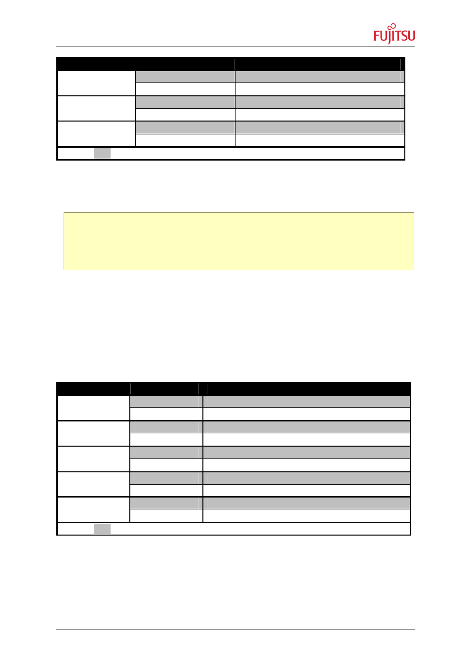
Jumper
Setting
Description
ON (closed)
AVcc is connected to MCUVcc
JP15
OFF (open)
AVcc is disconnected
ON (closed)
AVRH is connected to AVcc
JP16
OFF (open)
AVRH defined by resistor network
*1
ON (closed)
AVss is connected to GND
JP18
OFF (open)
AVss is disconnected
Default: grey
*1
By default the resistor network (R10 and R13) is not assembled on the board
Table 3-8: MCU ADC Supply
3.4.3 FlexRay CC Power Supply Voltage at SK-91F467-FLEXRAY
JP8
Connects 5V or 3.3V voltage supply to ASSPVcc
JP9
Connects 3.3V or ASSPVcc to ASSP voltage supply pin Vcc1 (3.3V by default)
JP13 Connects ASSP C-pin to 1.8V voltage supply
JP22 Connects ASSP pin 8 to 1.8V voltage supply
JP24 Connects ASSP pin 9 to GND
Jumper
Setting
Description
1-2
5V connected to ASSPVcc
JP8
2-3
3.3V connected to ASSPVcc
1-2
3.3V connected to ASSP Vcc1 pin
JP9
2-3
ASSPVcc connected to ASSP Vcc1 pin
ON (closed)
1.8V connected to ASSP C-pin
JP13
OFF (open)
1.8V not connected to ASSP C-pin
ON (closed)
1.8V connected to ASSP pin 8
JP22
OFF (open)
1.8V not connected to ASSP pin 8
ON (closed)
GND connected to ASSP pin 9
JP24
OFF (open)
GND not connected to ASSP pin 9
Default: grey
Table 3-9: FlexRay CC Supply
Note:
If JP15 or JP18 are open, the user has to supply an adequate analogue voltage supply (AVcc
and AVss) to the A/D-converter.
If JP16 is open, the potential divider comprising resistors R10 and R13 define AVRH.