Heat & Glo Fireplace HEAT & GLO TWILIGHT-II User Manual
Page 17
Heat & Glo LifeStyle Collection • Twilight-II • 2087-900 Rev. G • 12/05
17
E. Junction Box Installation
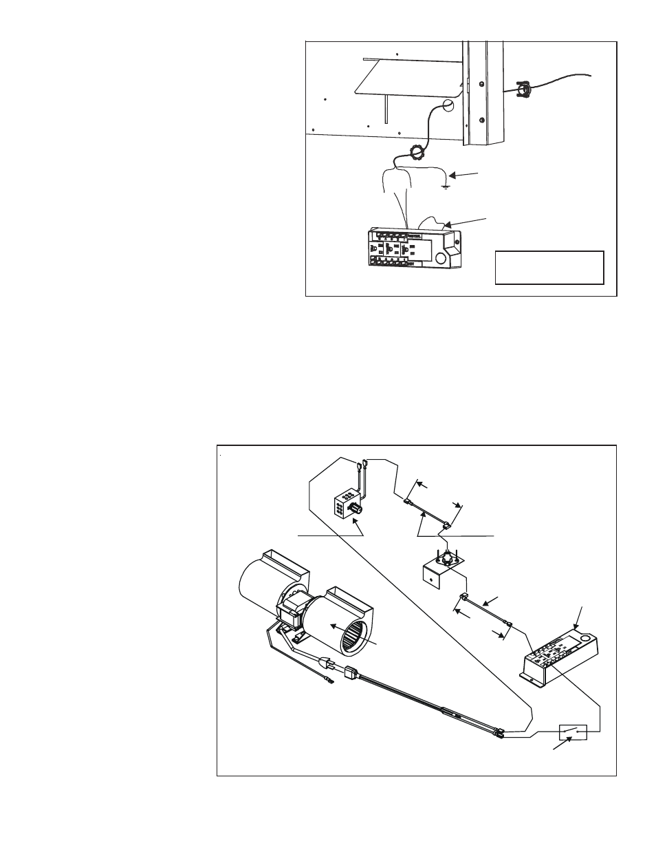
F. Wall Switch Installation for Fan (Optional)
If the box is being wired from the OUTSIDE of the
appliance:
•
Install the Romex
™
connector (not included
with appliance) in the side wrap.
•
Loosen two screws on the Romex connector,
feed the necessary length of wire through the
connector and tighten the screws.
•
Make all necessary wire connections.
Figure 7.4 Junction Box Detail
Figure 7.5 Junction Box Wired to Wall Switch
If the box is being wired to a wall
mounted switch for use with a fan
(See Figure 7.5):
•
The power supply for the
appliance must be brought into
a switch box.
•
The power can then be supplied
from the switch box to the
appliance using a minimum of
14-3 with ground wire.
•
At the switch box connect the
black (hot) wire and red (switch
leg) wire to the wall switch as
shown.
•
At the appliance connect the
black (hot), white (neutral) and
green (ground) wires to the junc-
tion box as shown.
•
Add a 1/4 inch insulated female
connector to the red (switch leg)
wire, route it through the knock-
out in the face of the junction
box, and connect to the top fan
switch connector (1/4 inch
male) as shown.
•
Loosen the two screws on the Romex connector, feed the
necessary length of wire through the connector and tighten the
screws.
•
Make all necessary wire connections to the receptacle and
assemble the receptacle and cover to the junction box.
If the box is being wired from the INSIDE of the
appliance:
•
Remove the screw attaching the junction box
to the outer shell, rotate the junction box
inward to disengage it from the outer shell
(see Figure 7.4).
•
Pull the electrical wires from outside the
appliance through this opening into the valve
compartment.
NOTE: Do NOT wire
110VAC to wall switch.
GREEN WIRE
INSIDE BOX
14/2WG
COPPER GROUND
ATTACHED TO GRN SCREW
WITH GRN WIRE
BLK
WHT
WHT
BLK
HEAT SHIELD
6 INCH
APPROX.
WIRE LEAD
1 MALE END
1 FEMALE END
TEMPERATURE
SENSOR SWITCH
WIRE LEAD
2 FEMALE ENDS
JUNCTION
BOX
6 INCH
APPROX.
FAN
SPEED CONTROL
(RHEOSTAT)
FAN
PLUG AND WIRE
ASSEMBLY
OPTIONAL
WALL SWITCH