ATL Telecom AM100 User Manual
Page 12
13
ATL User Guide
AM100 M
Modem
5.
CONFIGURATION
5.1
CONNECTING THE AM100
The AM100 comes packaged complete with a suitable power lead and an RJ45 to RJ11 line cord.
Connect the power lead to the rear of the unit.
Plug one end of the line cord into the RJ45 line connector on the rear of the unit. The other end
connects to your copper line pair.
A suitable Stub lead is required to connect the modem user interface on the rear of the unit to
your DTE equipment. Details of the interface pin out can be found in section 6.3.
5.1.1
LED POWER ON SEQUENCE - V.35 & X.21 VARIANTS
During the power on sequence the LED's will flash back and forth and when finished one Rate and
one Mode LED will be lit.
5.1.2
LED POWER ON SEQUENCE - G703 VARIANT
During the power on sequence the LED's will flash and when finished the status and data LED’s
will be lit.
3.2
CONFIGURING THE AM100
3.2.1
DATA LINK WITH NO EXTERNAL TIMING
(V.35 & X.21 VARIANTS)
This type of circuit is illustrated in Figure 1. One end of the link is configured as a MASTER and the
other end is configured as a SLAVE. The rate setting set at the MASTER unit will be downloaded
to the SLAVE automatically.
3.2.1.1
CONFIGURING THE SLAVE UNIT
Press the Mode button until the Slave LED is lit.
3.2.1.2
CONFIGURING THE MASTER UNIT
Press the Mode button until the Master Int Led is lit.
Press the Rate Button until the desired rate is lit red.
3.2.1.3
SYNCHRONISATION
If the units are correctly connected then, after a couple of minutes the Rate LED will turn Green.
The units are now synchronized and transmitting data to one another
12
ATL User Guide
AM100 M
Modem
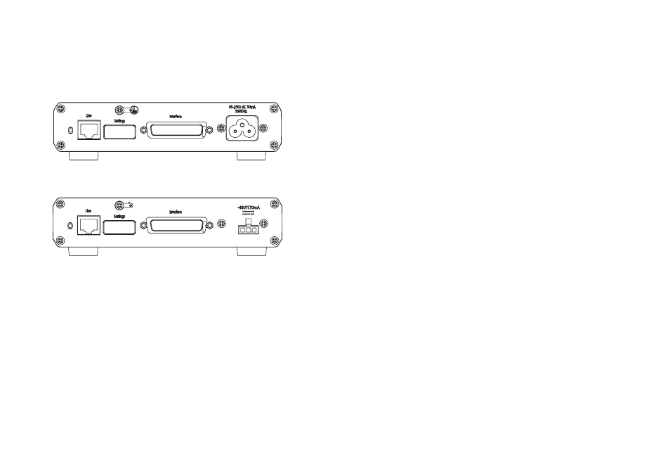
4.2
REAR PANEL
4.2.1
AC VARIANTS
4.2.2
DC VARIANTS
4.2,3
CONNECTORS
RJ45 Line connector
25 way D-type Interface connector
3 pin Mini Molex connector (DC variant)
3 pin IEC mains connector (AC variant)
4.2.4
CABLES
The AM100 is supplied with either an AC mains or DC cable ( ref Ordering Information). Plus a
Category 5 RJ45 to RJ11 line cord.