ATL Telecom AM100 User Manual
Page 11
11
ATL User Guide
AM100 M
Modem
4.1.2
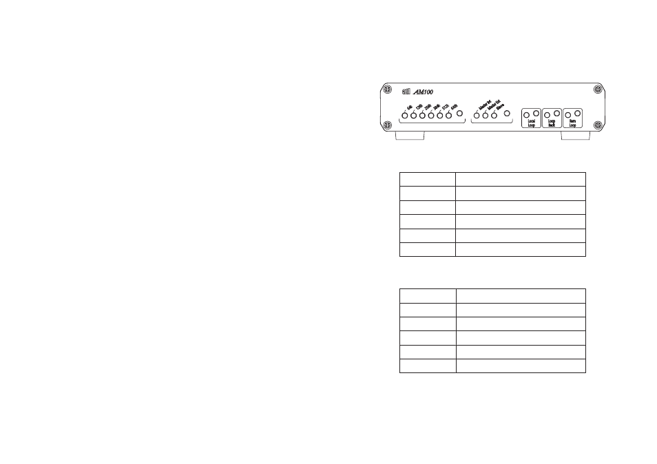
AM100 V.35 & X.21 VARIANTS
4.1.2.1
LEDS
4.1.2.2
BUTTONS
Button
Function
Local Loop
Turns Local Loop on and off
Loop Back
Turns Loop Back on and off
Rem Loop
Turns Remote Loop on and off
Rate Selection
Used to select the required rate (master
mode)
Mode Selection
Used to select the required mode
LED
Function
Rate Indication /
Status
Shows the transmission rate. Red when not in
sync, green when in sync
Mode Indication/
Data
Indicates the selected mode. Red when RXD
data is 1, green when RXD data is 0
Local Loop
Green when local loop is on
Loop Back
Green when loop back is on
Rem Loop
Green when remote loop is on
14
ATL User Guide
AM100 M
Modem
3.2.2
DATA LINK WITH EXTERNAL TIMING
(G.703, V.35 & X.21 VARIANTS)
This type of circuit is illustrated in Figure 2. This configuration is similar to the previous
configuration. The Master modem however can be set to receive an external timing source.
3.2.2.1
CONFIGURING THE SLAVE UNIT
Press the Mode button until the Slave LED is lit.
3.2.2.2
CONFIGURING THE MASTER UNIT (V.35 & X.21 VARIANTS)
Press the Mode button until the Master ext Led is lit.
Press the Rate Button until the desired rate is lit red.
3.2.2.2
CONFIGURING THE MASTER UNIT (G.703 VARIANT)
No configuration is required.
3.2.2.3
SYNCHRONISATION
If the units are correctly connected then, after a couple of minutes the Rate LED will turn Green.
The units are now synchronized and transmitting data to one another and timing is being
transferred from the customer equipment to the slave user interface.