6 electrical connection, 1 bus termination, 7 canopen interface – ifm electronic JN2100 v.2.2.0 User Manual
Page 7: 1 canopen functions
UK
Inclination sensor JN
7
6 Electrical connection
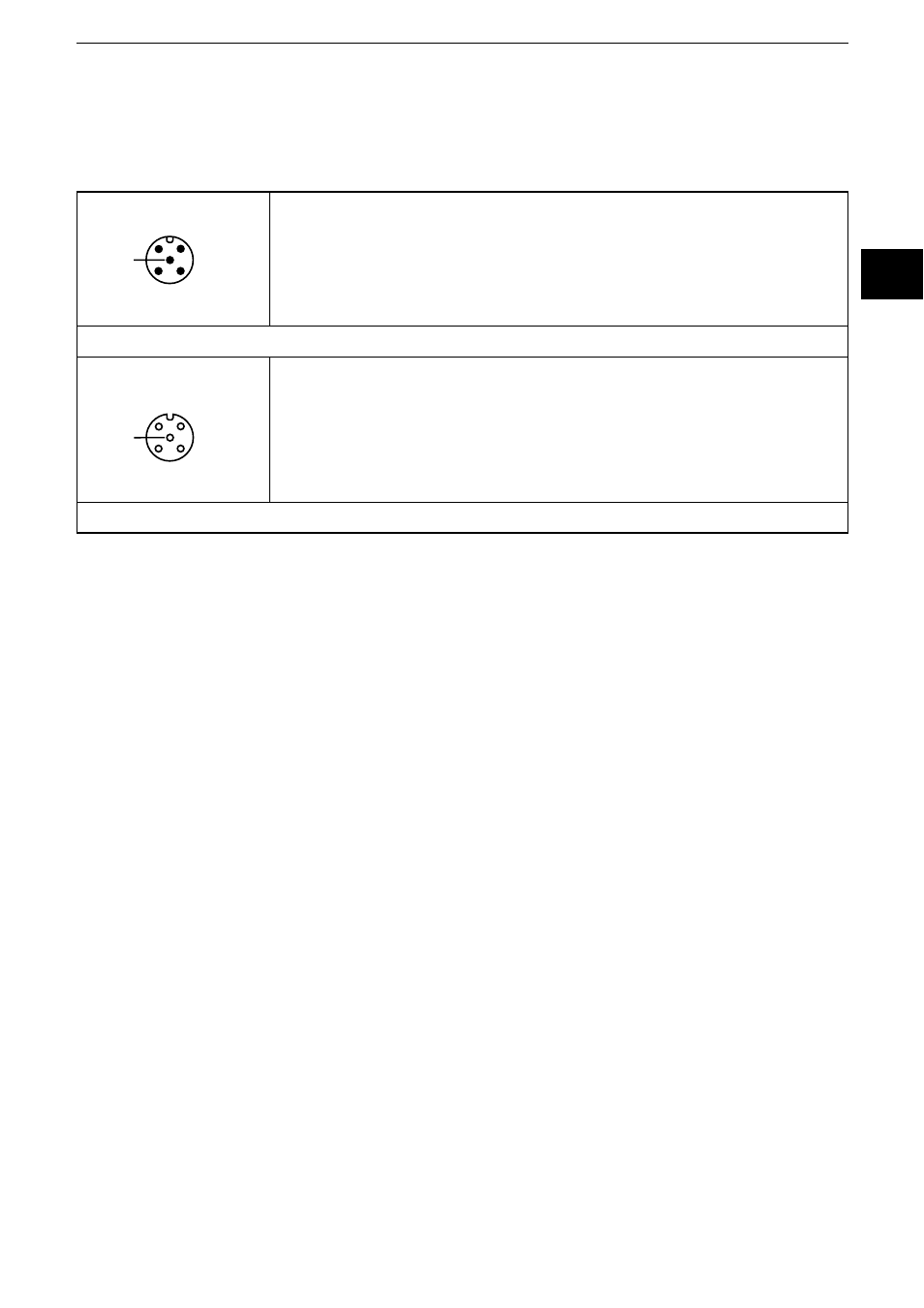
The inclination sensors are fitted with two round 5-pole M12 connectors (A-coded).
The pin connection corresponds to the CANopen specification CiA DR-303-1.
4
2
1
3
5
1: CAN_SHLD CAN shield
2: CAN_V+ Supply voltage 24 V DC (+U
B
)
3: CAN_GND Ground
4: CAN_H High bus cable
5: CAN_L Low bus cable
M12 connector CAN-In
3
1
2
4
5
1: CAN_SHLD CAN shield
2: CAN_V+ Supply voltage 24 V DC (+U
B
)
3: CAN_GND Ground
4: CAN_H High bus cable
5: CAN_L Low bus cable
M12 socket CAN-Out
6.1 Bus termination
The inclination sensors have an internal terminating resistor that can be activated
via the CANopen interface → SDO register.
7 CANopen interface
The inclination sensors have a standardised CANopen interface to CiA DS-301
and a device profile to CiA DSP-410. All measured values and parameters can be
accessed via the object directory (OD). The individual configuration can be saved
in the internal permanent memory (flash).
7.1 CANopen functions
The following CANopen functions are available:
● Several transmit data objects (TPDO) in four possible operating modes:
– individual check via a remote transmit-request telegram (RTR)
– cyclical transmission per interval time
– synchronised transmission after reception of a SYNC telegram
– a service data object (default SDO)
● Error messages per emergency object (EMCY) with support of the:
– general error register
– manufacturer-specific register
– error list (pre-defined error field)
● Monitoring mechanisms heartbeat and node guarding/life guarding