Mictor connector (j2), Mictor connector (j2) –13 – Altera Santa Cruz User Manual
Page 19
Chapter 2: Board Components
2–13
MICTOR Connector (J2)
© December 2008 Altera Corporation
Santa Cruz, USB, MICTOR, SD Card HSMC Reference Manual
lists the USB OTG transceiver board reference and manufacturing
information.
MICTOR Connector (J2)
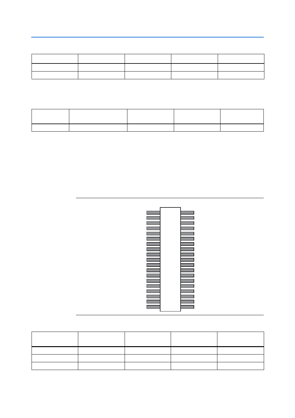
This section describes how to use the MICTOR connector (J2) on the THDB-SUM
board. The MICTOR connector can be used for logic analysis on the HSMC interface
host board by connecting an external scope or a logic analyzer to it.
shows the pin-outs of the MICTOR connector.
lists the detailed
pin mapping between the MICTOR connector and the HSMC connector.
31
USB_D2
54
HSPROTO_IO1
HSMC_RX_P1
32
USB_D1
50
HSPROTO_IO0
HSMC_RX_N0
Table 2–10. USB OTG Transceiver (U11) Pin Assignments (Part 2 of 2)
USB Pin Number
USB Signal Name
HSMC Pin Number
HSMC Signal Name
HSMC Pin Name
Table 2–11. USB OTG Transceiver Board Reference and Manufacturing Information
Board Reference
Description
Manufacturer
Manufacturing
Part Number
Manufacturer
Website
U11
USB OTG Transceiver
NXP Semiconductors
NXP ISP1504C
Figure 2–11. MICTOR Connector Pin-Outs
VHSMC
J2
3
5
7
1
9
11
13
4
6
8
2
10
12
14
15
17
19
16
18
20
21
23
25
27
29
31
33
35
37
22
24
26
28
30
32
34
36
38
NC
NC
MICTOR_CLK
MICTOR_D24
MICTOR_D23
MICTOR_TDO
MICTOR_D22
MICTOR_TCK
MICTOR_TMS
MICTOR_D20
MICTOR_D19
MICTOR_D18
MICTOR_D17
MICTOR_D16
MICTOR_D15
MICTOR_D14
MICTOR_TDI
NC
MICTOR_D21
NC
NC
TR_CLK
MICTOR_D13
MICTOR_D12
MICTOR_D11
MICTOR_D10
MICTOR_D6
MICTOR_D5
MICTOR_D4
MICTOR_D3
MICTOR_D2
MICTOR_D1
MICTOR_D0
MICTOR_D9
MICTOR_D7
VHSMC
MICTOR_D8
Table 2–12. MICTOR Connector (J2) Pin Assignments (Part 1 of 2)
MICTOR Connector
Pin Number
MICTOR Connector
Signal Name
HSMC Pin Number
HSMC Signal Name
HSMC Pin Name
5
MICTOR_CLK
156
MICTOR_CLK
HSMC_CLKIN_P2
6
TR_CLK
157
TR_CLK
HSMC_CLKOUT_N2
7
MICTOR_D24
132
MICTOR_D24
HSMC_RX_P13