Figure 2–10 – Altera Santa Cruz User Manual
Page 18
2–12
Chapter 2: Board Components
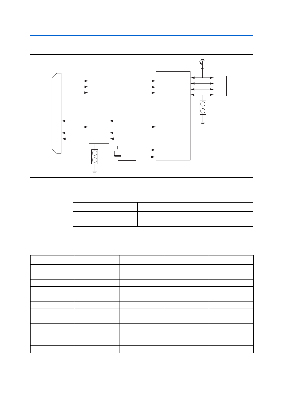
USB On-The-Go Transceiver (U11)
Santa Cruz, USB, MICTOR, SD Card HSMC Reference Manual
© December 2008 Altera Corporation
shows the JP2 configuration setting for the ID pin.
lists the detailed pin mapping between the USB OTG transceiver and the
HSMC connector.
Figure 2–10. USB OTG Transceiver and HSMC Connector Block Diagram
JP1 Open
Bus
Switches
(U1-U2)
USB_CLKOUT
HSPROTO_IO
HSMC Connector
(J1)
DATA[7:0]
CS
RESET
VBUS
DM
DP
ID
USB
Jack-Mini-USB-AB
JP2 Close = Host
Open = Device
USB_STP
USB_DIR
USB_NXT
DIR
STP
NXT
CLOCK
USB_D[7:0]
USB_CS_n
USB_RESET_n
NXP
ISP1504C
(U11)
XTAL1
XTAL2
XTAL1
XTAL2
X1
26 MHz
Table 2–9. ID Pin Configuration
JP2 Setting
Host or Peripheral Role
Open
Peripheral
Close
Host
Table 2–10. USB OTG Transceiver (U11) Pin Assignments (Part 1 of 2)
USB Pin Number
USB Signal Name
HSMC Pin Number
HSMC Signal Name
HSMC Pin Name
1
USB_D0
48
HSPROTO_RESET
HSMC_RX_P0
17
USB_RESET_n
86
HSPROTO_IO12
HSMC_RX_N6
19
USB_DIR
84
HSPROTO_IO11
HSMC_RX_P6
20
USB_STP
80
HSPROTO_IO10
HSMC_RX_N5
21
USB_NXT
78
HSPROTO_IO9
HSMC_RX_P5
23
USB_D7
74
HSPROTO_IO8
HSMC_RX_N4
24
USB_D6
72
HSPROTO_IO7
HSMC_RX_P4
25
USB_D5
68
HSPROTO_IO6
HSMC_RX_N3
26
USB_D4
66
HSPROTO_IO5
HSMC_RX_P3
27
USB_CLKOUT
62
HSPROTO_IO4
HSMC_RX_N2
28
USB_D3
60
HSPROTO_IO3
HSMC_RX_P2
29
USB_CS_n
56
HSPROTO_IO2
HSMC_RX_N1