Bryant 542E User Manual
Page 7
Attention! The text in this document has been recognized automatically. To view the original document, you can use the "Original mode".
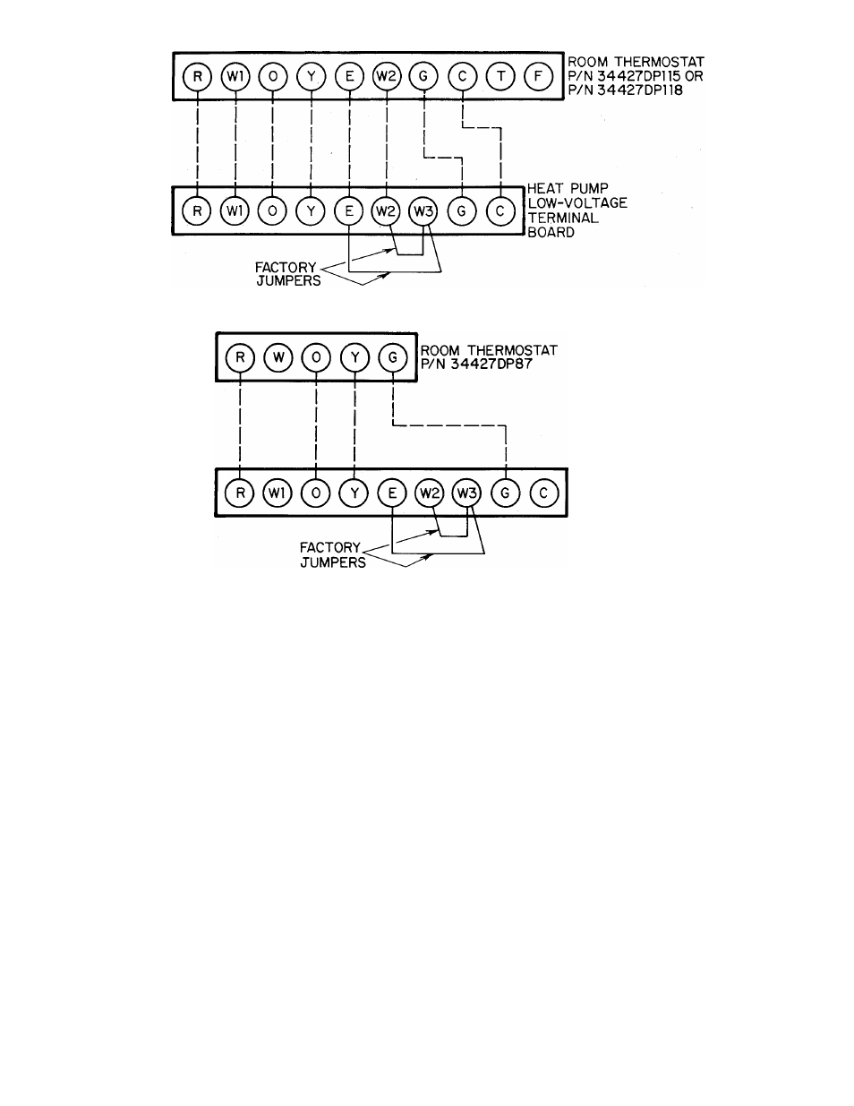
Figure 14—Field Low-Voltage Connections Using Room
Thermostat P/N 34427DP115or P/N 34427DP118
HEAT PUMP
LOW-VOLTAGE
TERMINAL
BOARD
Figure 15—Field Low-Voltage Connections Using Room Thermostat P/N 34427DP87
Mount the room thermostat on an inside wall in the space to
be conditioned. The thermostat should be approximately 4 or
5 feet above the floor and located where it will not be sub
jected to either a cooling or heating source, or direct ex
posure to sunlight.
Use No. 18 AWG “color-coded” insulated wires to make the
low-voltage connections between the thermostat and the
unit. If the thermostat is located more than 100 feet from
the unit as measured along the low-voltage wires, use No. 16
AWG wire.
A grommeted low-voltage inlet hole has been provided in the
control panel adjacent to the control access panel. See
Figure 3 or 4. Run the low-voltage thermostat leads thru the
inlet hole and to the low-voltage terminal board. See Figure
12. Complete the low-voltage thermostat connections as
shown in Figure 14 or 15, depending on which recommended
room thermostat is being used.
C. Heat Anticipator Settings
The recommended room thermostats have a fixed heat antic
ipator for heat pump heating. When using an accessory
electric heater to provide supplemental heat and emergency
heat capability for the system, see the Installation Instruc
tions packaged with the heater for setting the adjustable
second-stage heat anticipator.
V. PREPARING UNIT FOR STARTUP
WARNING/DANGER:
A failure to Inllow the-e in.struclion.'
could roiult in seiiou.-< person;.I injury:
1. Follow recognized safety practice.- and wear protective
goggles when checking or .servicing the refrigerant
2. Do not oper.ali' the compres.=or or pro\ ide any electric
power to thi- unil unles.s compre-.'or tormin.il co\ or i.- in
place and secured.
0. Do not rerno\e the compres.-or terminal cu\er iinli! all
electrical source- lia\e been di.sronnected.
1. If a rcl'ngeranl leak is su.-pi'Cted ,iround the com)!re.--or
terminals, relie\e all pres-utv from the -v-tem before
touching or di-ttirliing anything inside the tciminal
■7). .Sy-tem contani.- ml :ind refri.ger.int under pre.-.-tire. De
not use a torch to remove any component To remote a
component, wear protective goggles and [U'oceed as fol-
a. Shut oil electrical power to unit.
li. Reliete all pressure from sy-tem.
c. (7ut component connectin.g tubing with tubing ciit-
ti'i- and remove component from unit.
d. When nece.ssary. un.-weat remaining tubing -tubs
carefully. Oil may ignite when exposed to torch
ÎiisilïiïiSilSijîliSîiiïiiliillS^^
Proceed as follows to prepare the unit for initial startup:
1. Read and follow instructions on all WARNING, CAU
TION, and INFORMATION labels attached to the unit;
for example, blower rotation labels etc.
2. Visually inspect for oil at all refrigerant tubing connec
tions and on unit base. Detecting oil generally indicates
a refrigerant leak. Leak-test all refrigerant tubing con
nections, using electronic leak detector, halide torch, or
liquid-soap solution. If refrigerant leak is detected, see
Section VI, “Refrigerant Leaks,” in these instructions.
-
7
-