Iii. duct connections – Bryant 542E User Manual
Page 4
Attention! The text in this document has been recognized automatically. To view the original document, you can use the "Original mode".
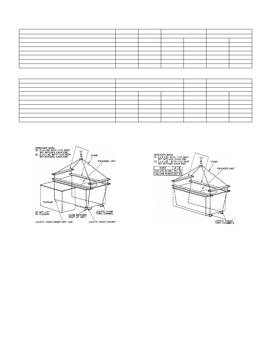
TABLE ll-ELECTRICAL DATA-MODEL 542E-SIZES 024 THRU 042
MODEL
542E
SIZE
024
030
036
042
SERIES
A
A
A
A
Unit Volts-Phase (60Hz)
208-230-1
208-230-1
208-230-1
208/230-3
230-1
208/230-3
Operating Voltage Range
197-253
197-253
197-253
187-253
207-253
187-253
Total Unit Amps
16.7
22.7
23.9
14.8
28.7
21.0
Max Branch Circuit Fuse Size (Amps)
30
45
45
25
50
40
Unit Ampacity for Wire Sizing
20.2
27.5
29.2
17.8
34.9
25.2
Minimum Wire Size (AWG)*
10
10
10
12
8
10
Maximum Wire Length (Ft)*
115
85
80
95
112
107
TABLE MI-ELECTRICAL DATA-MODELS 542E048, 542D060, & 542E060
MODEL
542E
542E
542D & 542E
SIZE
048
060
060
SERIES
A
A
A
Unit Volts—Phase (60Flz)
230-1
208/230-3
460-3
230-1
208/230-3
460-3
Operating Voltage Range
207-253
187-253
414-506
207-253
187-253
414-506
Total Unit Amps
31.9
22.4
10.9
40.9
26.1
13.7
Max Branch Circuit Fuse Size (Amps)
60
45
20
60
50
25
Unit Ampacity for Wire Sizing
38.9
27.1
13.2
49.8
31.3
16.4
Minimum Wire Size (AWG)*
8
10
14
6
8
12
Maximum Wire Length (Ft)*
101
100
181
123
137
229
*Only use copper wire for field connections to unit. Wire size is based on 60 or 75°C copper conductor at 86°F (30°C) ambient tempera
ture and ampacity shown in fable. If other than 60 or 75°C copper conductor is used, if ambient temperature is above 86°F, or if voltage
drop of wire exceeds 2% of unit rated voltage, determine wire size from ampacity shown and the National Electrical Code. Wire lengths
shown are measured one way along the wire path between unit and service panel for minimum voltage drop.
USE SPREADER BARS TO PROTECT UNIT
USE SPREADER BARS TO PROTECT UNIT
ONE INCH FROM PLENUM FOR
PROPER FIT ON CURB AND PLATFORM
CHAIN RETAINER FOR
PROPER BALANCE
Figure 7—542D060 Suggested Rigging
Prime the trap with water and check the condensate line for
leaks.
CAUTION;
Do not undersize the condensate drain line.
During the heating defrost cycle, defrost water from the
melting ice on the outdoor coil flows through the slots in the
heat pump base directly below the outdoor coil. If a field-sup-
plied drain pan is to be used to catch the defrost water, this
pan should be at least 2 inches high and extend at least 2 in
ches beyond the width and length of the unit.
If the installation requires draining the condensate and/or
defrost away from the unit, connect a minimum of 7/8-inch
OD copper tubing, 3/4-inch galvanized pipe, or 7/8-inch
plastic pipe. The drainage lines should pitch downward at a
slope of at least 1 inch in every 10 feet of horizontal run.
Both condensate and defrost water can be drained directly
onto the roof in rooftop installations where permitted or
onto a gravel apron in ground-level installations. When a
gravel apron is being used, it should extend at least 24 in
ches around the mounting pad to ensure proper drainage.
III. DUCT CONNECTIONS
Flanges are provided on the 542E supply- and return-air
A79148
Figure 8—542E Suggested Rigging
openings on the side of the unit. See Figure 3 for connection
sizes and locations. See Figures 10 and 11 for illustrations of
typical installations.
Flanges are provided on the 542D supply- and return-air
openings on the bottom of the unit. See Figure 4 for connec
tion sizes and locations.
NOTE:
The minimum installation requirements of the duct
system must be in accordance with the standards of the Na
tional Fire Protection Association for installation of air con
ditioning and ventilating systems of other than residence
type, NFPA No. 90; or residence type, NFPA No. 90B; and/or
local codes and ordinances.
CAUTION:
When the duct system fastening holes are being
drilled into the 542E side instead of the unit duct flanges
provided, use care to avoid puncturing the coil tubes.
The following criteria must be followed when selecting, siz
ing, and installing ductwork:
1. When electric heater is installed, a minimum clearance
of one inch to combustible materials must be main
tained for the first 36 inches of duct.
2. It is recommended that flexible connectors be used be-
-
4
-