D. unit controls and safety devices, Vili. sequence of operation, A. crankcase heater operation – Bryant 542E User Manual
Page 11: B. cooling operation
Attention! The text in this document has been recognized automatically. To view the original document, you can use the "Original mode".
2. Refer to Table Vl and determine airflow at static pres
sure measured.
When an accessory electric heater is being used, the system
airflow can also be determined by measuring the tempera
ture rise through the unit and using the following formula:
AIRFLOW (fts/min) = i
X Y
where,
KW = Heater nominal KW at 240 or 480V
TR = Measured température rise
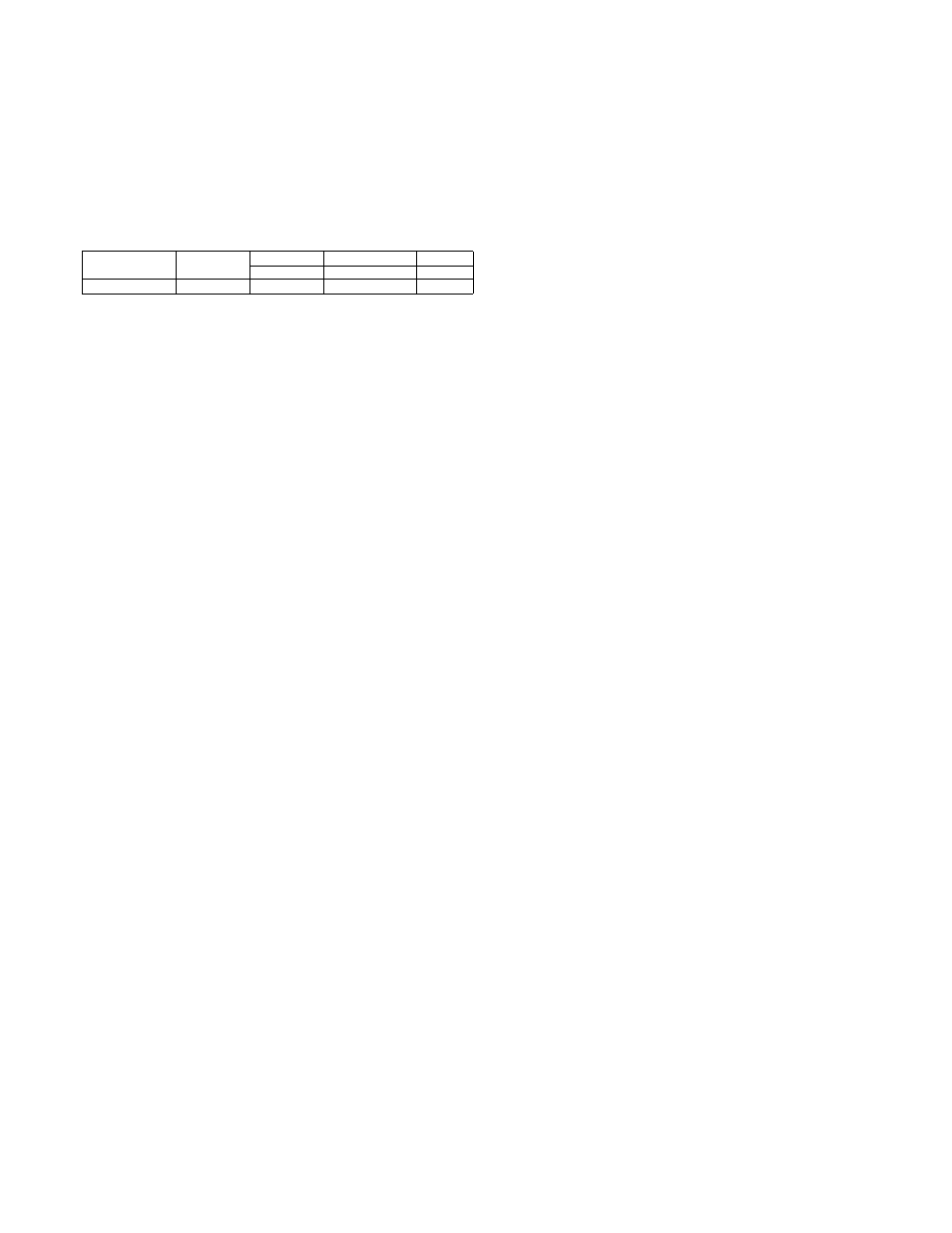
Y =
200V
208V
220V
230V
240V
440V
460V
480V
2195
2374
2655
2902
3160
NOTE: Value Y varies with the operating voltage at the heater.
Interpolate to determine the value of Y for voltages not
shown.
D. Unit Controls and Safety Devices
1. High-Pressue Relief VaZue—This valve, which is located
in the compressor, opens when the pressure differential
between the low and high side becomes excessive.
2. Compressor Internal Overload—Hhis overload, which is
located in the compressor, interrupts power to the com
pressor when the current and internal temperature
become excessive. It automatically resets when the
internal motor temperature drops to a safe level. It may
require up to 60 minutes or longer for this overload to
reset; therefore, if an internal overload is suspected of
being open, disconnect the electrical power to the unit
and check the circuit thru the overload with an ohm-
meter or continuity tester.
3. Low-Pressure Switch—This switch with automatic reset
interrupts the compressor control circuit when the re
frigerant high-side pressure becomes too low. It protects
the compressor from damage attributable to loss of the
refrigerant charge.
4. Time/Temperature Defrost System—The defrost control
system consists of a defrost timer, a defrost thermostat
switch, and a defrost relay. The system initiates defrost
cycle operation every 90 minutes if a coil icing condition
exists. See the defrost cycle sequence of operation in
Section VIII.
5. Crankcase Heater—This device prevents overdilution of
compressor oil with refrigerant during shutdown
periods, thereby extending the life of the compressor.
See the crankcase heater sequence of operation in Sec
tion VIII.
6. Compressor Quick-Start Componenis—These components
are used with all single-phase units to improve com
pressor starting characteristics.
7. Outdoor Fan Thermostat—This control, which is
featured on all 3-phase units, maintains the proper cool
ing mode condensing temperature by switching the
outdoor fan motor to high- or low-speed operation. Low-
speed fan operation permits low-ambient cooling opera
tion down to 40°F outdoor temperature.
Vili. SEQUENCE OF OPERATION
Do not leave the installation until the heat pump has been
observed throughout one or two complete cycles. The in
staller should make certain during this time that all compo
nents are operating in correct sequence.
The sequences of operation described in this section pertain
to all 208/230-volt, 3-phase units; however, the sequence of
operation of single-phase and 460-volt units is Very similar.
Refer to the line-to-line wiring diagram in Figure 16.
NOTE:
Although the actual unit wiring may vary slightly
from that shown in Figure 16, the sequence of operation will
not be affected. The sequences of operation described in this
section pertain to a typical system using room thermostat
P/N 34427DP115 or P/N 34427DP118 for system control,
and using an accessory electric resistance heater for supple
mental heat.
NOTE:
The indoor blower motor will operate continuously,
regardless of the room thermostat SYSTEM switch position,
when the FAN switch is in the ON position. The ON position
of the FAN switch keeps the circuit through blower relay
coil 2A closed and the coil energized. When the FAN switch
, is in the AUTO position, the blower operates only when the
system is started by the room thermostat demand for heat
ing or cooling.
A. Crankcase Heater Operation
Compressor crankcase heater llA is connected across nor
mally open compressor contractor 2D contacts between 13
and 23. When electric power is supplied to the heat pump,
and the unit is not operating in either the heating or cooling
mode, a completed circuit between power legs LI and L3 per
mits current to flow through one leg of compressor motor 3F
windings and through crankcase heater 11 A. The high
electrical resistance of the crankcase heater causes the
heater to heat up, while the compressor motor windings
serve only as a means of completing the circuit between LI
and L3.
When the heat pump receives a “call” for either heating or
cooling, normally open compressor contactor 2D contacts be
tween 13 and 23 are closed. (See heating and cooling
sequences of operation in this section.) Electric current,
which always follows the path of least resistance, now flows
through the closed contacts and through both compressor
motor 3F and outdoor fan motor 3D1. The crankcase heater,
which offers a much higher electrical resistance than the
two motors, receives virtually no electrical current as long
as the contactor is energized.
B. Cooling Operation
With the room thermostat SYSTEM switch in COOL posi
tion and the FAN switch in AUTO position, the cooling
sequence of operation is as follows:
When the room temperature rises to within 2 degrees of the
room thermostat temperature setting, the thermostat cool
ing operation bulb “makes” and thermostat terminal R is
connected to thermostat terminal 0. This completed circuit
through the thermostat completes the circuit through unit
terminal 0. Reversing valve solenoid coil 5B and outdoor fan
relay coil 2C are now connected across the 24-volt secondary
of unit transformer IB.
Energized solenoid coil 5B switches the reversing valve from
the normal heating mode position to the cooling mode posi
tion. Energized outdoor fan relay coil 2C closes its set of nor
mally open contacts between 1 and 3, and opens its set of
normally closed contacts between 1 and 2, permitting two-
speed outdoor fan motor 3D1 to operate on either high- or
low-speed depending on the outdoor ambient temperature.
NOTE:
When the contacts of outdoor fan relay coil 2C are in
their normal heating mode positions as shown in Figure 16,
fan motor 3D1 operates on high speed, regardless of the out
door ambient temperature.
The heat pump is now in a “standby” condition and ready to
operate in the cooling mode when the room thermostat
“calls” for cooling.
When the room temperature rises slightly above the ther
mostat temperature setting, the thermostat cooling bulb
“makes” and thermostat terminal R is automatically con
nected to thermostat terminals G and Y. These completed
circuits through the thermostat connect indoor blower relay
coil 2A (through unit terminal G) and compressor contactor
coil 2D (through unit terminal Y) across the 24-volt sec
-
11
-