FloAire Demand Control Ventilation System User Manual
Page 20
A0023662
May 2014 Rev.5
20
c. Display temperature readings
Starting from the Main menu, press the DOWN button. Screen displays
“Temperatures”. Press the
ENTER button. Press the UP and DOWN buttons to view all temperatures measured by the room and
duct temperature sensors.
d. Display Fan Monitoring data: Fan Frequencies and Motor Amps
Starting from the Main
menu, press the DOWN button until the screen displays “Monitoring”. Press
the ENTER button. Press the UP and DOWN buttons to alternate between “Fan Frequencies” and
“Motor Amps”. Press enter for either one to view Frequency of each VFD or amps drawn by the motor
on each fan.
e. Fan Proving Interlock: Calibration
If the Fan Proving Interlock option is enabled, Calibration is required at startup. To perform
calibration, make sure Test and Balance has been performed on the entire system first. Filters should
be in place.
Starting from the Main menu, press DOWN until the screen displays “Calibration”. Press ENTER. The
screen should display “Proving Calib. Calibrate?” Press ENTER again to start the Calibration process
which takes about 40 sec. Press MENU once when calibration is complete.
If Calibration is unsuccessful, the message “Calibration Fail” will appear. Make sure the VFDs are
running and the MUA interlock signal is wired correctly to ILxA ILxB.
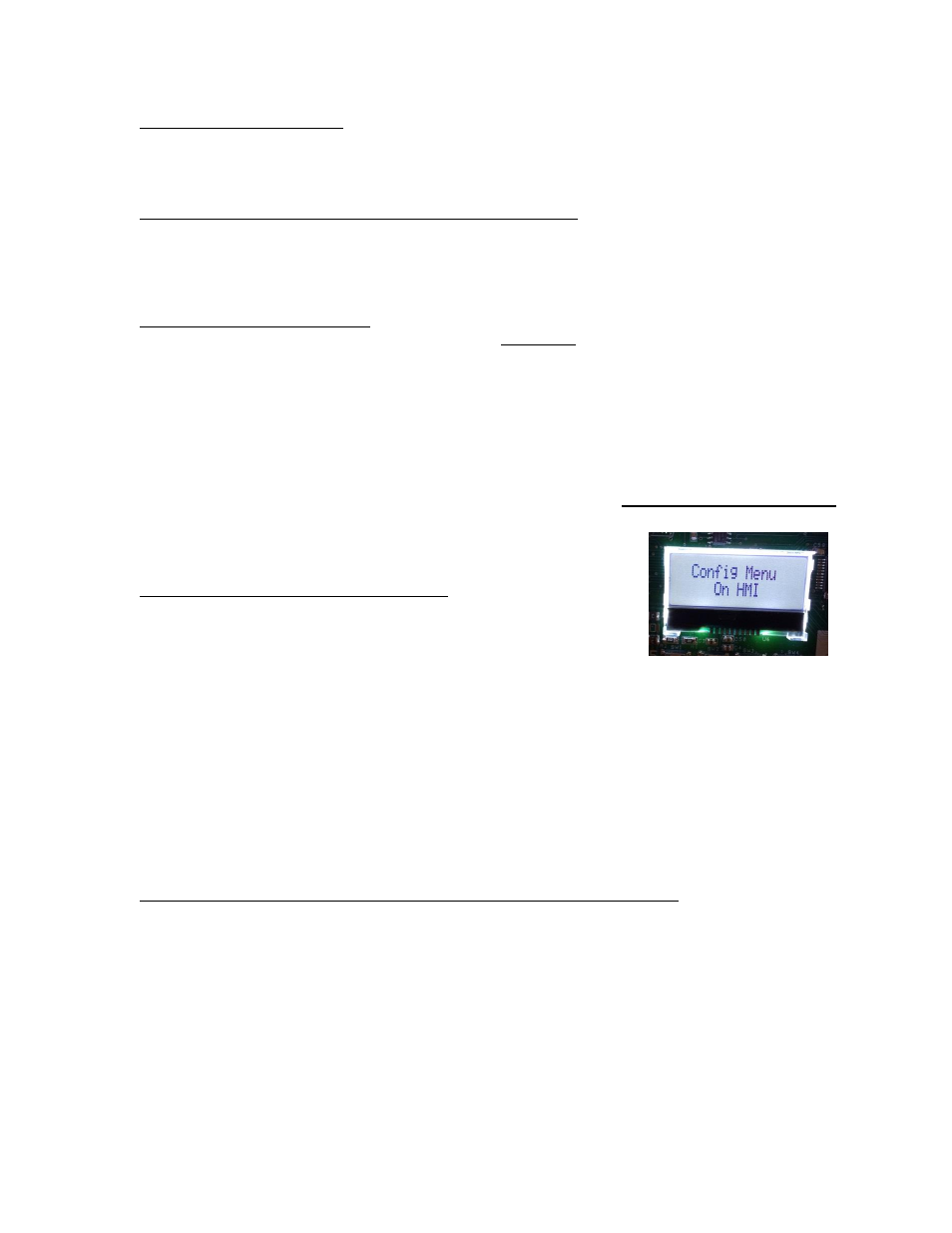
All the items below are for Configuration and are accessed by putting the HMI into Configuration mode.
To do this, starting from the Main menu on the ECPM03 LCD, press the MENU button. Screen displays
“Configuration” Press the ENTER button. Screen will display “Config Menu
on
HMI”. From there, the rest can be done on the HMI.
f.
Configure Temperature Sensor Assignments
Starting from the Main menu of HMI, screen displays
“Temp Sensor
Assignment
”. Press ENTER. Screen displays “Select Temp Sens to
assign: 1
”.
To navigate to another Temperature sensor, press the UP button. To
configure the assignment for a Temperature Sensor, press ENTER.
1. For Temperature sensor 1, the options are either to follow the room sensor wired to terminal T1A,
T1B (
“Room Temp 1”) or to assign a preset room temperature (75°F by default). Press UP or
DOWN to choose the proper option. Press MENU to confirm the selection. To change the default
preset value, press the ENTER button when displaying the Preset Temperature. Press UP or
DOWN to change the preset value. Press MENU multiple times to get out to main menu.
2. For Temperature sensor 2 and above, the options are either control or monitor. To control the fan
the choice should be capture volume or riser followed by the fan number. To monitor the
temperature. The decision should be one out of the list: Auxiliary Temp, Hood Coil Input, Hood
Coil Output, PSP Discharge, or ACPSP Discharge.
Press MENU multiple times to get back to the main menu or one more time to reboot the processor.
g. Configure Temperature Sensor Offset values (Factory Default: 15 Degrees °F)
Starting from the Main menu of HMI, press DOWN once so
screen displays “Temp Sensor Offset”.
Press ENTER. Screen displays “Select Temp Sens to Offset: 2”
Press UP or DOWN to navigate between the different Duct Temperature sensors. Press ENTER to
select one. Then press UP or DOWN to adjust the offset Temperature.
Press MENU multiple times to get back to the main menu or one more time to reboot the processor.