Mower drive belt removal, Mower drive belt replacemertt, Mower drive belt adjustment – Craftsman 917.254611 User Manual
Page 22: Level mower housing, Side-to-side mower adjustment, Repair and adjustment
Attention! The text in this document has been recognized automatically. To view the original document, you can use the "Original mode".
REPAIR AND ADJUSTMENT
BELT
EXTENSION
SPRING
L.H.
MANDREL
COTTER PIN
ENGINE
PULLEY
IDLER BELT
GUIDE
ROCK SHAFT
ASSEMBLY
EXTENSION
SPRING
BRAKE
ROD
BOLT
L.H. PIVOT
BRACKET
R.H. PIVOT
BRACKET
FIGURE 33
LIFT
LEVER
FIGURE 34
NUT"C”
NUT"B"
23. Mower Drive Belt Removal
NOTE: MOWER BELT INSTALLATION DECAL LOC
ATED ON MOWER HOUSING.
REPUCE ONLY WITH THE BELTS SPECIFIED IN THIS
MANUAL.
a. Place attachment clutch lever in "Disengaged” posi
tion (Fig 30).
Move Attachment lift lever {Fig 30) forward to lower
mower to Us lowest position
Roll belt off engine pulley.
Pull belt off both mower deck pulleys
b.
c.
d
e.
FIGURE 3S
Spring belt guide away from idler pulley and pull belt
off idler pulley
f Slide belt from under extension spring
24. Mower Drive Belt Replacemertt
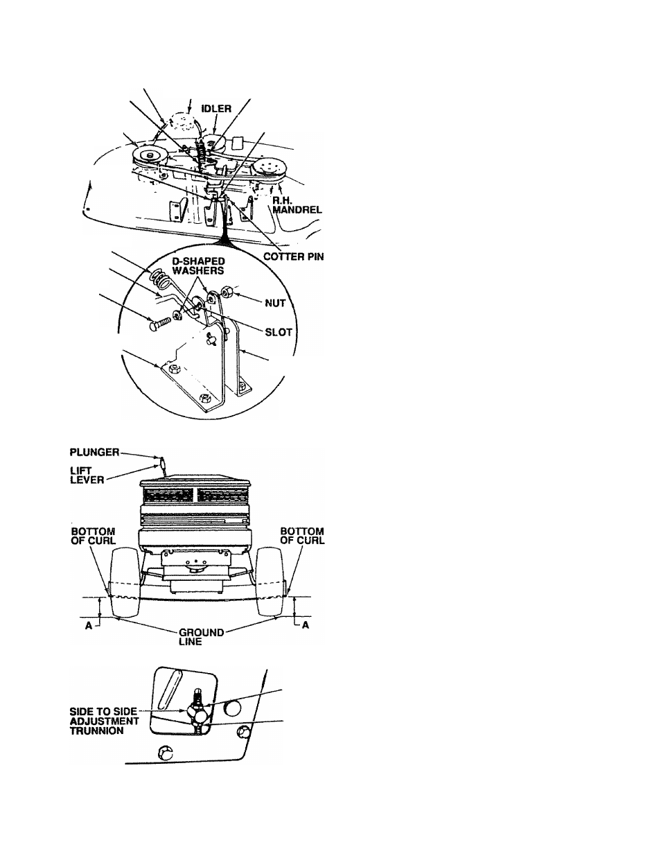
a Slide belt under extension spring (Fig, 33),
b Place bett on rear side of both mandrel puiieys
c Spring idler belt guide down and place belt around
rear side of idler pulley
d Roll belt over engine pulley
e. Make sure belt is inside all bell guides.
NOTE: WHEN INSTALLING A NEW BELT, EXTENSION
SPRING MUST BE RETURNED TO LOWER END
OF
SLOT
(ORIGINAL
POSITION)
ON
ROCK
SHAFT ASSEMBLY.
25. Mower Drive Belt Adjustment
Your tractor has been manufactured with the ability to read
just the mower drive belt to provide you with longer belt life.
If the attachment clutch lever travels 4-1/2" (11.43 cm) up
the slot in the dash before spring resistance is evident ad^
iustment is necessary. NOTE: CHECK FOR PROPER
ipHING TENSION WITH THE ENGINE OFF AND THE
LIFT LEVER IN THE HIGHEST POSITION.
a Lower the mower deck for easier access
b Using (2) 7/16" wrenches, remove the bolt, nut & D-
Shaped washers (Fig 33 - inset).
c Move extension spring from lower end of slot to up
per end in rock shaft assembly and install bolt, nut &
the D-Shaped washers
d Tighten bolt and nut to secure the D-shaped wash
ers (flat side down).
26. Level Mower Housing
Adjust the mower while tractor is parked on level ground or
driveway. Make sure lire pressure is correct, if tires are over
or under infiated, you will rrot properly adjust your mower
SIDE-TO-SIDE MOWER ADJUSTMENT
a Depress lift lever plunger and use lift lever to raise
mower to maximum cutting height {Fig. 31).
b.
Measure height from bottom of curl to ground line at
front of mower. Distance "A" should be the same on
both sides (Fig. 34).
c.
if distance “A” needs to be changed, snap out ac
cess hole cover on L.H. side above footrest Use
11/16” wrench on nuts "B” and "C" at side-to-side
adjustment trunnion (Fig. 35),
d To raise left side of mower, loosen nut “B" and
tighten nut “C"
e To lower left side of mower, loosen nut “C" and
tighten nut "B".
22