Attaching the auger tube to the frame, Warning – Wheatheart X Series 13 Augers User Manual
Page 58
3. A
SSEMBLY
W
HEATHEART
- X13 S
ERIES
A
UGERS
3.14. A
TTACHING
THE
A
UGER
T
UBE
TO
THE
F
RAME
X1374, X1384, X1394
58
30787 R1
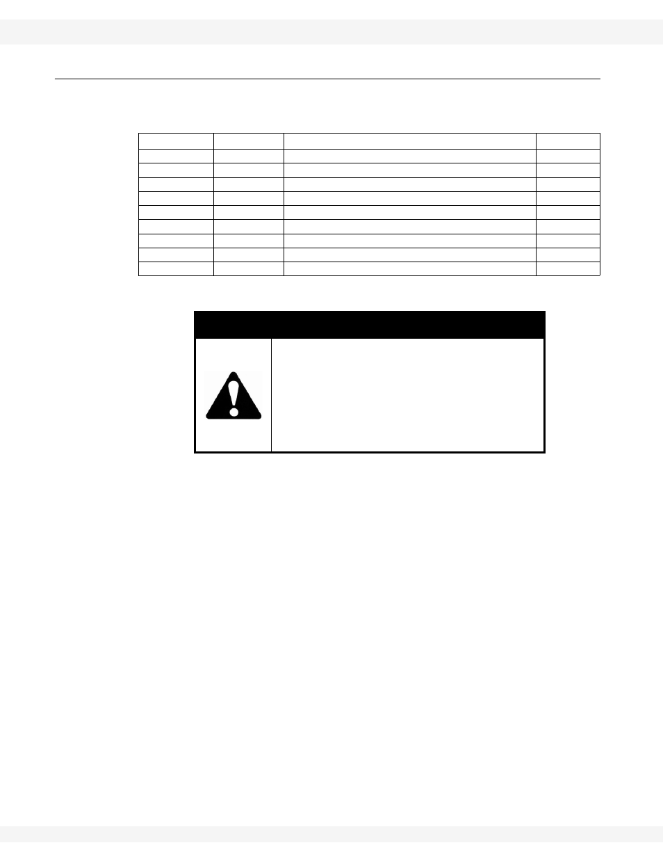
3.14. ATTACHING THE AUGER TUBE TO THE FRAME
Table 3.12. provides a list of parts required to attach the auger tube to the frame.
1. Ensure that the four frame attach spacers are loosely installed on the upper
and lower tube attach brackets (see Figure 3.23).
2. Arrange a strong sling around the auger tube. Attach the sling to a crane,
block and tackle, or a front end loader, and lift the auger tube high enough to
remove the stands from underneath the auger.
3. Move tube over top of the assembled frame, ensuring that the tube is
centered on the scissor frame before proceeding.
4. Connect tube to the lower frame arms:
a. Lift the lower frame arms to align with the lower frame attach spacers.
b. Grease the 1-3/4" x 19" lower frame attach pin.
c. Insert stabilizer brackets between the lower frame arm and the tube frame
attach spacers, and insert them through the lower frame arm tube
connection flange holes, stabilizer brackets, and through the frame attach
spacers.
d. Secure the lower frame attach pin with 5/16" x 2-1/2" roll pins.
Table 3.12. Parts Required, Attaching the Auger Tube to the Frame
X130-74/84
X130-94
Description
Amount
29950
29950
Stabilizer brackets
2
29952
29953
Stabilizer braces
2
29995
29995
1-3/4” x 19” lower frame attach pin
2
28584
28584
5/16” x 2-1/2” roll pin
4
20079
20079
1-3/4” x 18” upper scissor frame attach pin
2
28584
28584
5/16” x 2-1/2” roll pin
2
27589
27589
5/8” x 2-1/2” bolts
1
19991
19991
5/8” x 2” bolts
1
19600
19600
5/8” locknuts
2
WARNING
Components are heavy and create a crushing
and pinching hazard if improperly handled. Be
sure to use proper hoisting equipment and
procedures, and ensure lifting apparatus is
secure before working around or under the
raised components. Failure to do so may
cause serious personal injury.