Suggested conditions to keep unit level – Wood’s Powr-Grip CB1 User Manual
Page 11
Rev 1.0/6-13
9
CB1: #35168
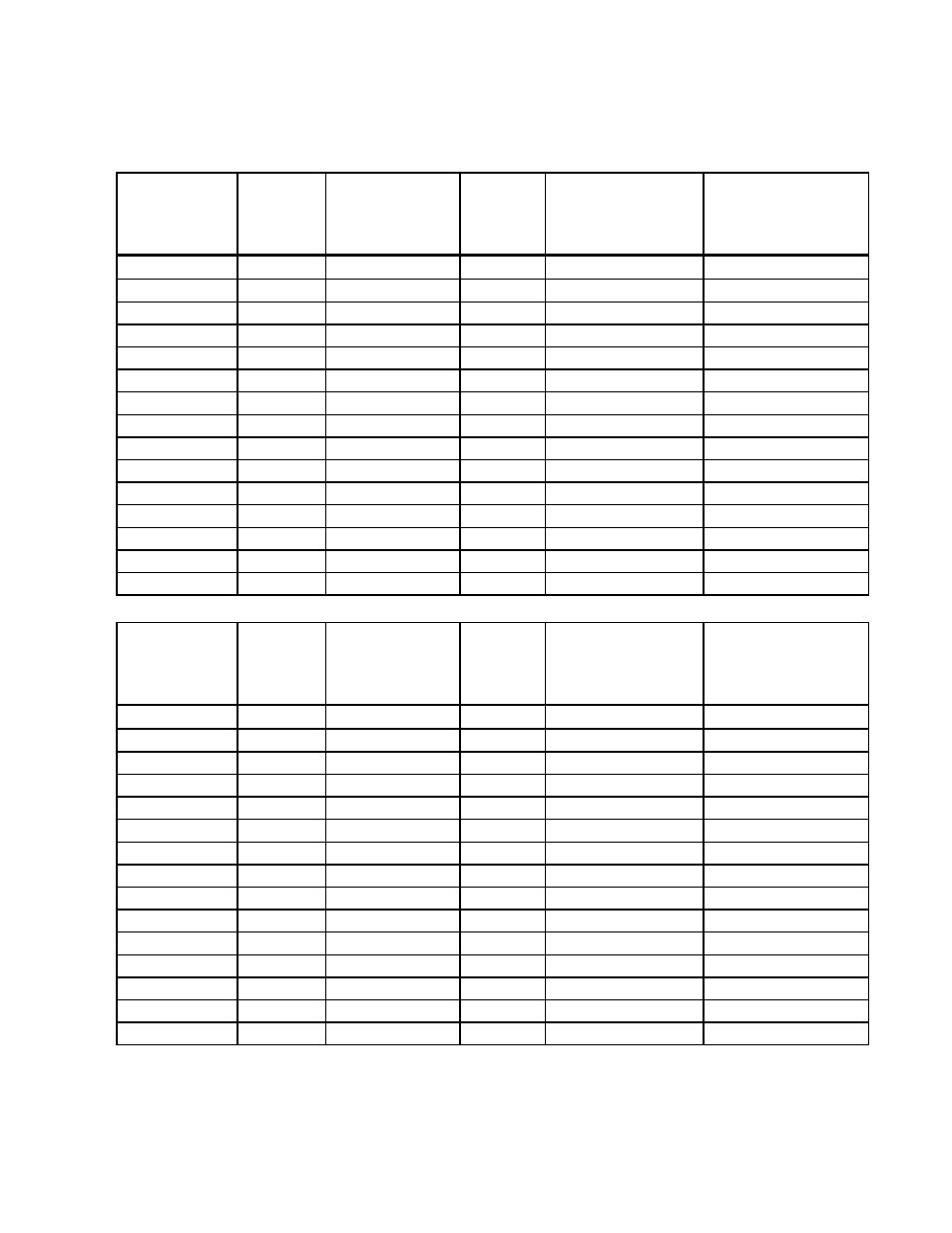
SUGGESTED CONDITIONS
TO KEEP UNIT LEVEL
CHART 1
SHORTEST REACH, LIFT POSITION #6
A
B
C
D
E
F
OVERALL
COUNTERWEIGHT
CONTROL LINE #2
CONTROL LINE #1
LOAD
LENGTH
ARM
BALLAST
FRONT [unloaded]
REAR [loaded]
(lbs)
(inches)
POSITION ID.
(lbs)
(lbs)
(lbs)
0
156
#A
0
66
-
100
156
#A
0
66
27
200
156
#A
11
83
83
300
156
#A
37
124
124
400
168
#B
19
153
153
500
180
#C
3
178
178
600
180
#C
21
214
214
700
192
#D
4
233
233
800
192
#D
18
266
266
900
204
#E
1
281
281
1000
204
#E
14
313
313
1100
204
#E
27
344
344
1200
216
#F
8
353
353
1300
216
#F
19
383
383
1400
216
#F
30
412
412
CHART 2
LONGEST REACH, LIFT POSITION #1
A
B
C
D
E
F
OVERALL
COUNTERWEIGHT
CONTROL LINE #2
CONTROL LINE #1
LOAD
LENGTH
ARM
BALLAST
FRONT [unloaded]
REAR [loaded]
(lbs)
(inches)
POSITION ID.
(lbs)
(lbs)
(lbs)
0
156
#A
10
0
-
100
168
#B
5
43
43
200
168
#B
33
85
85
300
180
#C
21
118
118
400
192
#D
9
148
148
500
192
#D
29
184
184
600
204
#E
15
208
208
700
216
#F
2
228
228
800
216
#F
16
261
261
900
216
#F
30
294
294
1000
216
#F
44
326
326
1100
216
#F
59
359
359
1200
216
#F
73
391
391
1300
216
#F
87
424
424
1400
216
#F
101
456
456
"Load" is the weight of the material being lifted.
"Overall length" is measured from the face of the pads to the opposite end of the Counter-Balancer.
"Ballast" is the weight that must be added to the Counter-Balancer, in the counterweight enclosure.
"Control lines" are used to control the Counter-Balancer with or without the load.