Wood’s Powr-Grip MRTALP6FS10TDC User Manual
Page 7
Rev 2.0/5-14
5
CF13CEO: #35178AFT
5) Repeat steps #1-4 to install the second T-arm assembly, as shown in the preceding
illustration.
6) To remove T-arm assemblies, reverse this procedure. Store removed T-arm assemblies in a
clean, dry location to protect them from environmental exposure. Set the vacuum pads
facing upward, because prolonged pressure against the sealing rings may cause them to
become distorted.
Note: The bolts connecting the cross member to the extension arm on each T-arm assembly
may be removed, allowing you to reposition the cross member laterally on the extension arm.
Depending on the vacuum lifter used, such an adjustment may be required to keep a desired pad
configuration symmetrical. Precise alignment of the vacuum pads may be essential to attach the
lifter on architectural panels with high contours and/or narrow spacing between contours that run
the length of the panel. Position the cross members of both T-arms so that each cross member
is centered on the rotation axis (not centered on the extension arm). Be sure to tighten the bolts
securely each time after you reposition a cross member on its extension arm.
T
O
C
ONNECT
/D
ISCONNECT
V
ACUUM
H
OSES
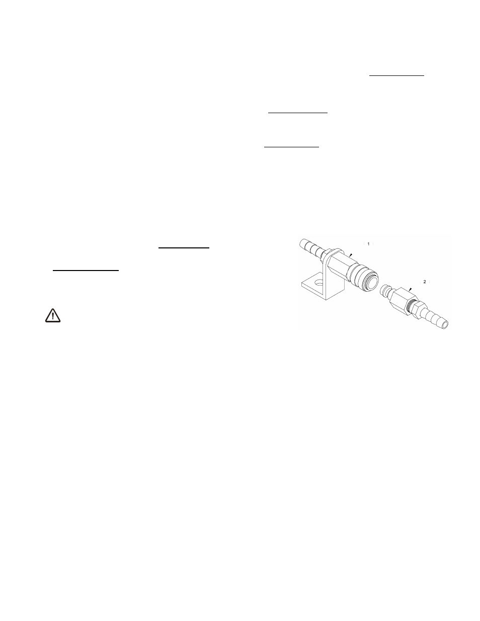
The vacuum hose for each vacuum pad is connected to or
disconnected from the lifter's vacuum system by means of
a quick connector. To connect the vacuum hose, push the
male and female ends of the connector together until they
lock. To disconnect the vacuum hose, move the release
ring on the female end until the connector separates.
WARNING: Make sure vacuum hoses are
coiled or routed to avoid
damage during rotation or tilt.
Make sure all vacuum hoses are secure and routed to avoid
being punctured, pinched, kinked, entangled, abraded or otherwise damaged while the lifter is in
operation.
Note: Since MRT4-DC lifters do not come equipped with quick connectors, a quick connector kit
enables the use of T-arm assemblies (see REPLACEMENT PARTS LIST).
QUICK CONNECTOR
1 FEMALE END
2 MALE END