Assembly – Wood’s Powr-Grip MRTALP6FS10TDC User Manual
Page 6
Rev 2.0/5-14
4
CF13CEO: #35178AFT
ASSEMBLY
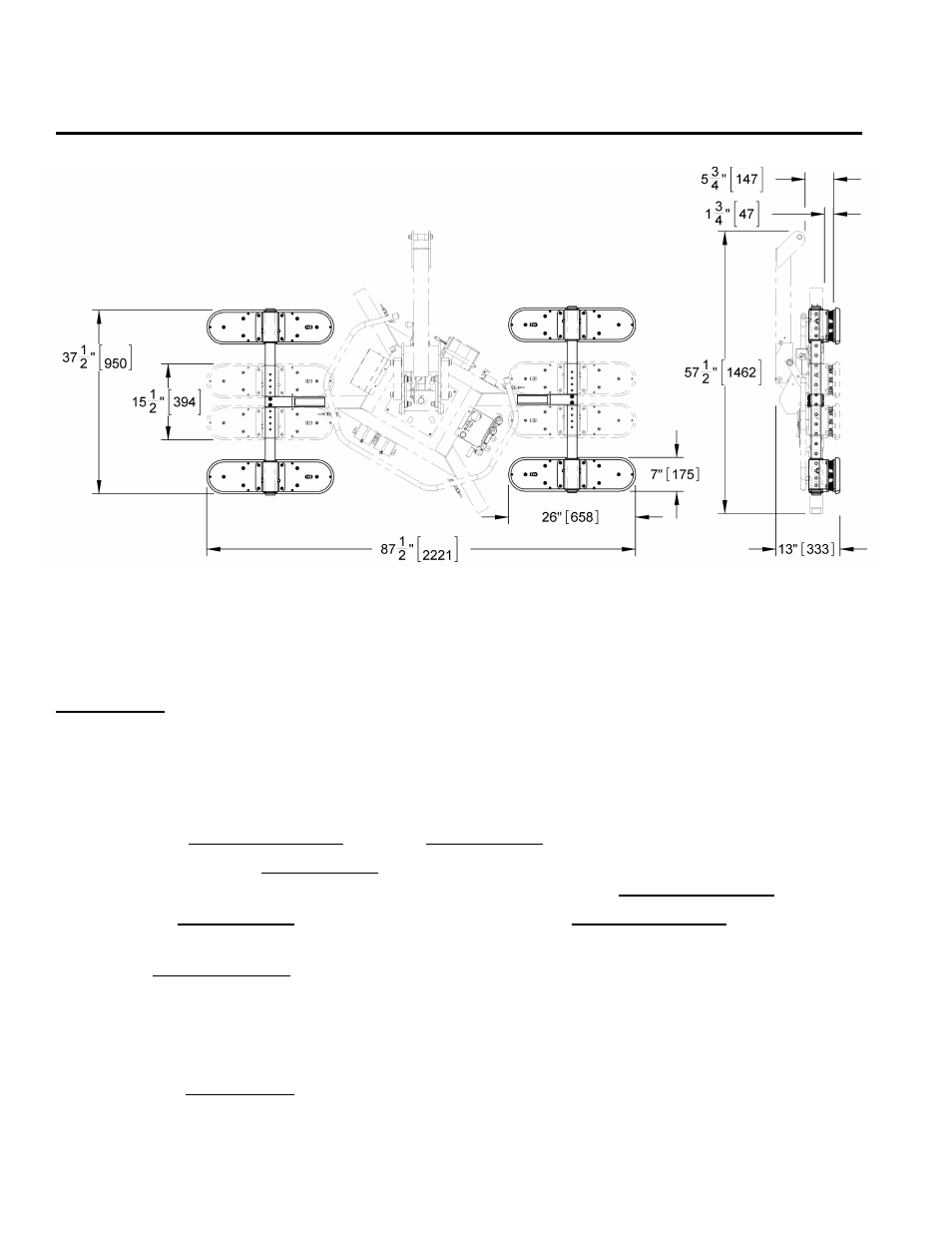
MRTA-DC shown with Pad Frame T-Arm Assemblies and VPFS625 pads.
Note: For illustration only―Pad Spread dimensions may vary.
Assemble the vacuum lifter as directed in the lifter's instruction manual. However, instead of the
standard extension arms and vacuum pads, install the 2 Pad Frame T-Arm Assemblies with all 4
vacuum pads and connect all the vacuum hoses, as directed in the following sections. Note: Use
only 2 pads on each T-arm assembly.
T
O
I
NSTALL
/R
EMOVE
T-A
RM
A
SSEMBLIES
1) Remove the cotterless hitch pin from the extension arm of one Pad Frame T-Arm Assembly.
2) Insert the end of the extension arm as far as possible into its socket on the lifter's main pad
frame (see preceding illustration), so that the holes align for the cotterless hitch pin.
3) Secure the extension arm in the pad frame by pushing the cotterless hitch pin through the
holes until the retaining ball emerges on the far side of the pad frame socket.
4) Use the quick connectors to connect the 2 vacuum hoses on each T-arm assembly to the
nearest available connection points on the main pad frame, as directed in the section T
O
C
ONNECT
/D
ISCONNECT
V
ACUUM
H
OSES
to follow.
Note: If the lifter is equipped with a dual vacuum system, 2 air-line circuits are identified by
color-coded vacuum hoses. In order to ensure maximum effectiveness of the dual vacuum
system, the vacuum pads must be connected in an equal and alternating distribution to the 2
circuits.