IOGear GCE616U User Manual
Page 7
1
2
3
4
5
1
2
3
7
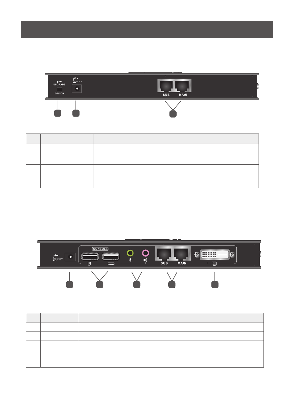
Rear View on Local Unit
GCE611U / GCE616U
No
Component
Description
1
F/W Upgrade Switch
Use this switch to turn on the firmware upgrade mode. Reset the power
to proceed with the firmware upgrade.
Switch it off and reset the power to return to normal mode.
2
Power Jack
The cable from the DC Power adapter connects here.
3
Sub / Main
The 2 Cat5e cable that connects the Remote and Local Units plugs in
here.
Rear View on Remote Unit
GCE611U / GCE616U
No
Component
Description
1
Power Jack
The cable from the power adapter connects here.
2
USB
The USB cable for your keyboard / mouse plugs in here.
3
Audio Ports
These mini stereo ports are for the speakers (green) and microphone (pink).
4
Sub / Main
The 2 Cat5e cable that connects the Remote and Local Units plugs in here.
5
DVI-D Port
This DVI port is for connecting to a compatible monitor.