Compliance table – Hellenbrand H-125 Series User Manual
Page 36
36
The regenerant piston (the small diameter one behind the
main piston) is removed from the main piston by press-
ing sideways and unsnapping it from its latch. Chemically
clean this in dilute sodium bisulfite or vinegar, or replace the
regenerant piston if needed. To remove the main downflow
or upflow piston fully extend the piston rod and then unsnap
the main piston, from its latch by pressing on the side with the
number. Chemically clean this in dilute sodium bisulfite or
vinegar, or replace the main piston.
Reattach the main piston to the drive cap assembly. Reattach
the regenerant piston (if needed) to the main piston. Do not lu-
bricate the piston rod, main piston or regenerant piston. Lubri-
cant will adversely affect the clear lip seals. Reinsert the drive
cap assembly and piston into the spacer stack assembly and
hand tighten the drive cap assembly. Continue to tighten the
drive cap assembly using a screwdriver as a ratchet until the
black o-ring on the spacer stack assembly is no longer visible
through the drain port. Excessive force can break the notches
molded into the drive back plate. Make certain that the main
drive gear still turns freely. The exact position of the piston is
not important as long as the main drive gear turns freely.
Reattach the drive assembly to the control valve and connect
all plugs. After completing any valve maintenance, press
and hold NEXT and REGEN buttons for 3 seconds or unplug
power source jack (black wire) and plug back in. This resets
the electronics and establishes the service piston position.
This display should flash all wording, then flash the software
version and then reset the valve to the service position.
Spacer Stack Assembly
To access the spacer stack assembly remove the drive as-
sembly, drive cap assembly and piston. The spacer stack
assembly can be removed easily without tools by using thumb
and forefinger. Inspect the black o-rings and clear lip seals for
wear or damage. Replace the entire stack if necessary. Do
not disassemble the stack.
The spacer stack assembly may be chemically cleaned (dilute
sodium bisulfite or vinegar) or wiped with a soft cloth.
The spacer stack assembly can be pushed in to the control
valve body bore by hand. Since the spacer stack assembly
can be compressed it is easier to use a blunt object (5/8" to
1-1/8" in diameter) to push the center of the assembly into the
control valve body. The assembly is properly seated when at
least four threads are exposed (approximately 5/8". Do not
force the spacer stack assembly in. The control valve body
bore interior can be lubricated with silicone to allow for easy
insertion of the entire stack. Do not use silicone or any other
type of lubricant on the clear lip seals or the piston.
Reattach the drive cap assembly and the piston(s) and the
drive assembly.
Figure 29
After completing any valve maintenance, press and hold
NEXT and REGEN buttons for 3 seconds or unplug power
source jack (black wire) and plug back in. This resets the
electronics and establishes the service piston position. The
display should flash all wording, then flash the software ver-
sion and then reset the valve to the service position.
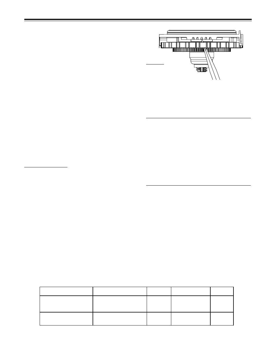
Injector Cap, Screen, Injector Plug and Injector Replacement
Unscrew the injector cap and lift off. Loosen cap with special
plastic wrench or pliers if necessary. Attached to the injector
cap is a screen. Remove the screen and clean if fouled.
Reattach the drive cap assembly and the piston(s) and the
drive assembly.
After completing any valve maintenance, press and hold
NEXT and REGEN buttons for 3 seconds or unplug power
source jack (black wire) and plug back in. This resets the
electronics and establishes the service piston position. The
display should flash all wording, then flash the software ver-
sion and then reset the valve to the service position.
Injector Cap, Screen, Injector Plug and Injector Replacement
Unscrew the injector cap and lift off. Loosen cap with special
plastic wrench or pliers if necessary. Attached to the injector
cap is a screen. Remove the screen and clean if fouled.
The plug and/or injector can be pried out with a small screw-
driver. The plug can be wiped clean. If the plug leaks replace
the entire plug. The injector consists of a throat and a nozzle.
Chemically clean the injector with vinegar or sodium bisul-
fite. The holes can be blown out with air. Both pieces have
smaller diameter holes that control the flow rates of water to
insure that the proper concentration of regenerant is used.
Sharp objects, which can score the plastic, should not be
used to clean the injector. Scoring the injector or increasing
the diameter of the hole could change the operating param-
eters of the injector.
Two holes are labeled DN and UP. Check for compliance.
See Table Below.
COMplianCe Table
Push the plug(s) and/or injectors firmly in place, replace the screen and hand tighten the injector cap.
Application
Injector and/or Plug(s)
Main Piston
Regenerant Piston
Stack
H125 Downflow
Injector in "DN" hole,
151-V3407
15-V3174
151-V3430
Softener or Regenerating
Plug in "UP" Hole
Filter (1.32" Distributor)
H125 Backwash Only
Plug in "DN" and "UP" holes, 151-V3407
None
151-V3430
Filter (1.32" Distributor)
Install Refill Port Plug