Front cover and drive assembly – Hellenbrand H-125 Series User Manual
Page 23
23
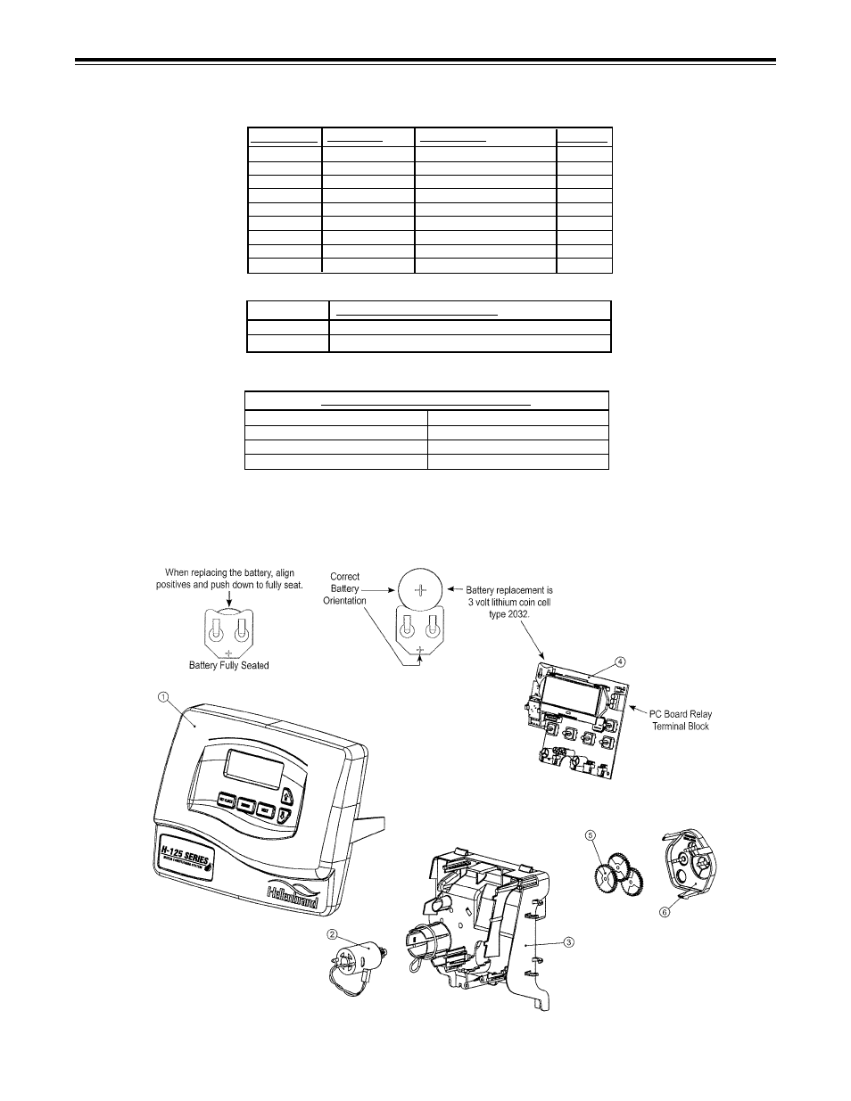
frOnT COver anD Drive asseMblY
The relay supplies 2 sets of dry contacts for user applications. The wiring of these
contacts is application specific.
NOTE:
Board Revision 219 and higher - there is a connection for twin alternating
system.
Relay Socket
65-SH2B-O5C (2 pole socket)
Relay
65-RH2B-VT DC12V (12V DC DPDT magnetic relay)
RELAY MODEL AND DESCRIPTION
1
15-V3529-01-H125
Front Cover Assembly Black
1
2
15-V3107-01
Motor Assembly
1
3
15-V3106-01
Drive Bracket & Spring Clip
1
4
15-V3578HP
H125 PC Board
1
5
15-V3110
Drive Gear 12x36
3
6
15-V3109
Drive Gear Cover
1
Not Shown
99-316-A001-K
Optional Relay Kit-PCM
1
Not Shown
99-316-A002-K
Optional Relay Kit-120V Pigtail
Not Shown
15-V3009
Auxilliary Switch Kit
QUANTITY
DRAWING NO. ORDER NO.
DESCRIPTION
Relay Specifications: To insure proper fit and correct operation the following relay
and relay socket manufactured by Idec or the exact equivalent should be used.
PC Board Relay Terminal Block
Relay Socket
RLY 1
#13
V+ (Center)
#14
RLY 2 (Bottom)
WIRING FOR CORRECT ON/OFF OPERATION