Cycle sequence, Brine reclaim – Hellenbrand H-125 Series User Manual
Page 15
15
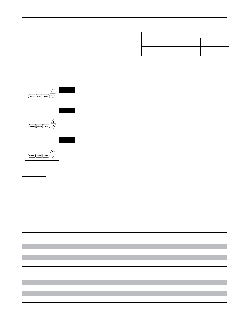
STEP 1 CS – Press NEXT and simultaneously for five seconds or until display changes and
release. Then press NEXT and simultaneously again for 5 seconds and release. If screen in
step 2CS does not appear in 5 seconds the lock on the valve is activated.
STEP 2 CS – Meter Size. Use the or to select from 1.0", 1.25", 1.50", 2.0" meter. H125 is a
1.25" meter. It is necessary to select meter size to coincide with control valve size used. Press
NEXT to go to Step 3C.
STEP 3CS – Use the or to select on of the following:
• OFF; or
• Brine Reclaim – Step 4CS; or
• Twin Alternating System – Step 6CS; or
• No Hard Water Bypass During Regeneration – Step 7CS.
• Factory Setting is OFF
Step 1CS
CYCle seQuenCe
Anytime cycle sequence is modified, softener set-up will revert to
manufacturer setting and must be reprogrammed as desired.
Cycle Sequence instructions allows the operator to set the order of the
cycle. The Softener System Setup allows the operator to set how long
the cycles will last. The operator may choose up to 9 cycles in any order.
END must be used as the last cycle option. The SERVICE cycle should
only be used in brine prefill applications to allow salt to dissolve.
Cycle Options
BACKWASH
FILL
RINSE
SOFTENING
END
Step 2CS
1.25
SET
Step 3CS
OFF
AUX VALVE CONTROL
SET
The following is an example of how to set a valve so that when regeneration is initiated, BACKWASH occurs first, REGENERANT
DRAW DN occurs second, RINSE occurs third, and FILL occurs fourth.
REGENERANT
DRAW-DN
brine reClaiM
Brine Reclaim: When Reclamation Mode is ENABLED, a portion of the unused brine is diverted after it has passed through the resin
bed. Brine discharge contains unused salt that can be used for brine make-up for the next regeneration. A motorized alternator valve
(MAV) must be connected to the two-pin connector labeled ALTERNATOR DRIVE located on the circuit board or error code 106 will
result. The MAV diverts the brine discharge to brine tank. A-Port discharges to brine tank. B-Port discharges to drain. Start time and
duration settings are for specified pressures, if variation occurs on site, elution study can be done to provide settings that optimize salt
savings without sacrificing capacity. For detailed instructions, see Brine Recovery instructions (73-355-BR).
Programming needed for Brine Recovery:
1. Start Time
2. Duration
3. Lower Salt Setting
start time / duration / salt setting - 10 lbs./ft
3
Water Pressure
H125-32-10
H125-48
H125-64
35 PSI
40:00/10:00/2.0
40:00/12:00/3.3
46:00/11:00/4.2
45 PSI
36:00/8:45/2.0
38:00/11:00/3.3
44:00/11:00/4.3
55 PSI
33:00/8:30/2.0
36:00/11:00/3.3
41:00/8:30/4.0
65 PSI
32:00/7:45/2.0
35:00/9:45/3.0
40:00/7:40/4.0
start time / duration / salt setting - 10 lbs./ft
3
Water Pressure
H125-96
H125-128
H125-160
H125-192
35 PSI
46:00/13:00/6.0
48:00/12:00/8.0
50:00/12:00/10.3
50:00/10:00/12.0
45 PSI
44:00/11:00/6.5
46:00/11:00/8.0
48:00/10:00/10.3
48:00/9:30/12.0
55 PSI
41:00/10:40/6.0
43:00/9:45/8.0
45:00/9:40/10.0
45:00/8:30/12.0
65 PSI
40:00/10:00/6.0
42:00/8:55/8.0
44:00/8:55/10.0
44:00/7:50/12.0