8 ground pin, 9 network connections – Media Technology Systems ION8.8 User Manual
Page 16
Page 16 of 31
Aug‐09
ground
anomalies
in
large
systems
where
signals
may
be
routed
from
remote
sources
with
the
opportunity
for
ground
anomalies,
it
is
common
practice
to
‘lift’
the
shield
on
one
end
(only)
of
the
cable
to
minimize
ground
loops.
Under
any
and
all
circumstances,
for
safety,
check
and
make
sure
that
proper
A/C
and
systems
grounding
is
practiced.
Your
MTSI
ION
is
designed
in
keeping
with
correct
safety
grounding
approved
under
international
accepted
standards.
It
is
also
designed
with
an
understanding
of
the
‘Real‐
World’
circumstances
of
systems
installation.
The
instrumentation
differential
input,
the
signal
grounding
practice
and
other
build
aspects
are
designed
to
provide
the
minimum
opportunity
for
A/C
and
signal
borne
noise
and
interference
to
contaminate
your
program
material
and
system
functionality.
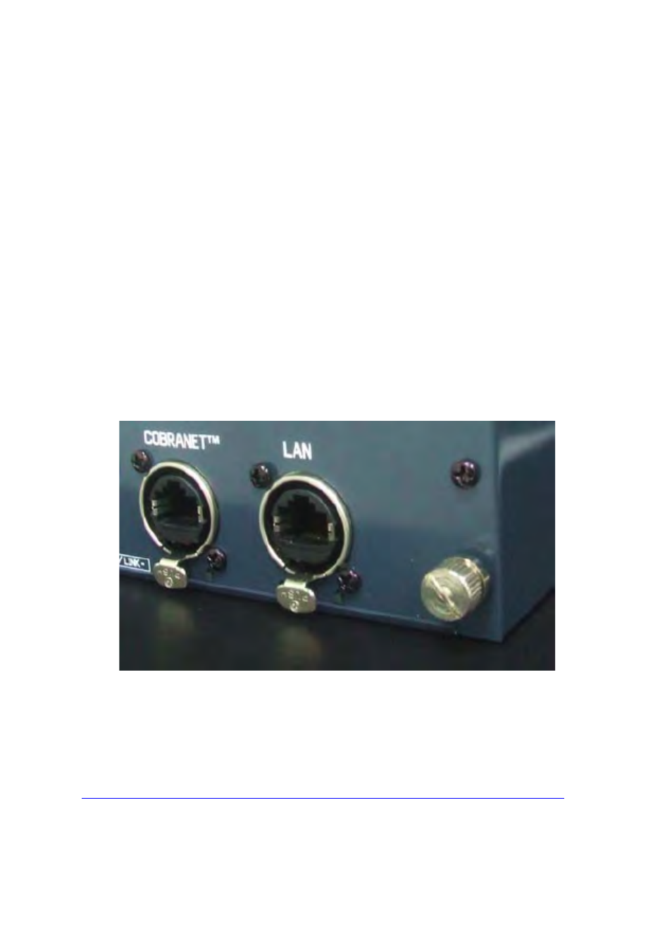
3.8 Ground Pin
Both
the
ION4.4
and
ION8.8
have
a
rear
panel
mounted
ground
pin
(bottom
right
of
the
rear
chassis
panel
–
see
Figure 3-6
below.
The
24volt
external
power
supply
is
ungrounded
and
the
rear
panel
ground
pin
has
been
provided
as
a
means
of
connecting
the
interface
to
a
good
ground.
This
may
be
necessary
if
the
ION
interface
(particularly
the
ION4.4)
is
located
outside
a
rack
and
a
ground
reference
is
needed
to
minimize
noise.
Figure 3-6: Rear chassis panel showing ground pin
3.9 Network connections
The
MTS
ION
uses
the
Neutrik
Ethercon
socket
to
provide
a
more
secure,
robust
connection.
Please
download
the
Ethercon
assembly
manual
from
the
Neutrik
website…
http://www.neutrik.com/client/neutrik/media/downloads/Media_240701762.pdf
NOTE:
Be
careful
to
remove
the
RJ45
tab
if
you
are
adding
the
Ethercon
shell
to
the
RJ45
connector,
otherwise
you
will
not
be
able
to
remove
the
assembly
from
the
Ethercon
socket.